


NOTE: DIAGRAMS & ILLUSTRATIONS ARE NOT TO SCALE.
27
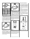
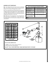
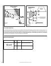
Figure 47
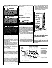
Step 8. Reassemble the remaining components
by reversing the procedures outlined in the
preceding steps.
Step 9. Attach the conversion label provided
in the conversion kit to the rating plate on the
appliance.
Step 10. Turn on gas supply and test for gas
leaks.
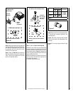
Step 7. (Refer to Figure 44 on Page 26)
A. Remove the orifice from the manifold and
replace it with the one provided in the kit. See
the following table for orifice sizes for natural
and propane models. Figure 47 illustrates the
orifice. Use pipe joint compound or Teflon tape
when installing the orifice.
B. Retrieve the burner and slide the venturi tube
over the orifice. Set the burner assembly into
its position and secure it.
C. Reinstall the grate assembly.
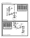
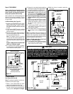
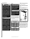
Step 5. Attach manometer to the manifold side
pressure test fitting and verify manifold pres-
sure reads 3.5 inches water column (0.87 kPa)
for natural gas, and 10.0 inches water column
(2.49 kPa) for propane gas.
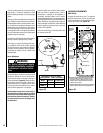
Step 6. Refer to Figure 46 and remove the
pilot hood assembly to access the hexed pilot
orifice. Remove and replace the orifice with
the one provided with the kit.
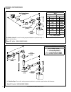
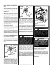
SIT Millivolt Gas
Valve Shown
Pressure
Regulator
Remove
These
Components
Figure 45
Millivolt & Electronic Gas Valves
HI
LO
SIT Electronic Gas Valve
Pressure
Regulator
SIT Millivolt Pilot Assembly Shown
Figure 46
Pilot
Orifice
Thermopile
(on millivolt
pilot assem-
blies only)
Millivolt & Electronic Pilot Assemblies
SIT Electronic Pilot
Pilot
Orifice
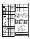
Model Orifice Size Elevation
Feet (meters)
Nat. Prop.
LSM40-2 .1405"
(#28)
.086"
(#44) 0-4500
(0-1372)
LSM45-2 .161"
(#20)
.093"
(#42)
Table 7