


10
NOTE: DIAGRAMS & ILLUSTRATIONS ARE NOT TO SCALE.
Remove the word "of" from sentence (in red below) (done 8-1-07)
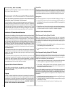
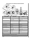
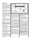
T
ermination
Flashing An
d
Storm Collar
Fires
top/Spacer
SV
8
6/12/24/36/48
V
ent Section
s
40' Ma
x
(12.2 M)
6' Mi
n
(1.8 M)
1" (25 mm
)
Minimum
Clearance to
Combustibles
Figure 12A
Figure 12B
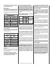
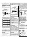
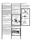
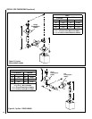
For vertical venting above 12 feet, in addition
to the restrictor (Figure 12A) an air inlet baffle
has to be installed over the grate as shown
in Figure 12B.
AIR INLET BAFFLE
GRATE
VENT RESTRICTOR INSTALLATION
RESTRICTOR
APPLIANCE VENT OUTLET
Install the restrictor as shown from
inside the unit, in the inner fireplace collar.
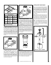
When vertically terminating the vent system above
the roof, install a vent restrictor in the top vent of
the fireplace outlet.
Figure 13
Step 3. INSTALL THE VENT SYSTEM
General Information
These instructions should be used as a guide-
line and do not supersede local codes in any
way. Install vent according to local codes,
these instructions, the current National Fuel
Gas Code (ANSI-Z223.1) in the USA or the
current standards of CAN/CGA-B149.1 and
-B149.2 in Canada.
These fireplaces are designed, tested and
listed for operation and installation with,
and only with, Secure Vent™ (SV8) Direct
Vent System Components, manufactured
by Security Chimneys International.
These approved vent system components
are labeled for identification. DO NOT
use any other manufacturer's vent com-
ponents with these appliances.
These fireplaces must be vented directly
to the outside.
The vent system may not service multiple
appliances, and must never be connected to a
flue serving a solid fuel burning appliance. The
vent pipe is tested to be run inside an enclosing
wall (such as a chase). There is no requirement
for inspection openings in the enclosing wall at
any of the joints in the vent pipe.
Select Venting System - Horizontal or Verti-
cal
With the appliance secured in framing, de-
termine vent routing and identify the exterior
termination location. The following sections
describe vertical (roof) and horizontal (ex-
terior wall) vent applications. Refer to the
section relating to your installation. A list of
approved venting components is shown on
Pages 24 and 25.
VERTICAL TERMINATION SYSTEMS (ROOF)
Figures 12A, 12B on Page 10 and Figures 22
through 24 on Pages 13 and 14 and their asso-
ciated Vertical Vent Tables illustrate the various
vertical venting configurations that are possible
for use with these appliances. A Vertical Vent
Table summarizes each system’s minimum and
maximum vertical and horizontal length values
that can be used to design and install the vent
components in a variety of applications.
The vertical vent system terminates through
the roof. The minimum vent height above the
roof and/or adjacent walls is specified in ANSI
Z223.1-(latest edition) (In Canada, the current
CAN-1 B149 installation code) by major build-
ing codes. Always consult your local codes
for specific requirements. A general guide to
follow is the Gas Vent Rule (refer to Figure 4
on Page 6).
For vertical venting from 6 feet to 12 feet or
more, from the top of the fireplace to the top
of the termination, the installation of a vent
restrictor is required.
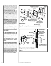
Install a vent restrictor (provided) in the appli-
ance flue outlet as shown in Figure 12A. It is
held in place by friction, only.
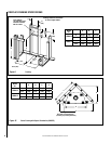
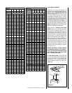
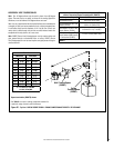
Vertical (Straight) Installation
(Figure 13)
Determine the number of straight vent sections
required. 4-1/2" (114 mm), 10-1/2" (267 mm),
22-1/2" (572 mm), 34-1/2" (876 mm) and 46-
1/2" (1181 mm) net section lengths are available.
Refer to the Vent Section Length Chart.