


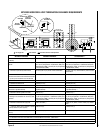

NOTE: DIAGRAMS & ILLUSTRATIONS ARE NOT TO SCALE.
11
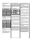
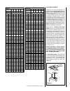
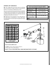
TRAHCHTGNELNOITCESTNEV
lanimoN
htgneLnoitceS
)sehcni(
6 21 42 63 84
T
O
T
A
L
Q
T
Y
noitceSteN
)sehcni(htgneL
2/1-4 2/1-01 2/1-22 2/1-43 2/1-64
tneVfothgieH snoitceStneVforebmuN
sehcni tf
5.4 573.0 1 0 0 0 0 1
9 57.0 2 0 0 0 0 2
5.01 578.0 0 1 0 0 0 1
51 52.1 1 1 0 0 0 2
5.91 526.1 2 1 0 0
0
3
12 57.1 0 2 0 0 0 2
5.22 578.1 0 0 1 0 0 1
5.52 521.2 1 2 0 0 0 3
5.13 526.2 0 3 0 0 0 3
5.43 578.2 0 0 0 1 0 1
5.73 521.3 1 1 1 0 0 3
5.34 526.3 0 2 1 0 0 3
54 57.3 0 0 2 0 0 2
5.64 578.3 0 0 0 0 1 1
5.94 521.4 1 0 2 0 0 3
15 52.4 1 0 0 0 1 2
5.55 526.4 0 1 2 0 0 3
75 57.4 0 0 1 1 0 2
66 52.5 0 2 2 0 0 4
5.76 526.5 0 0 3 0 0 3
96 57.5 0 0 0 2 0 2
27 6 1 0 3 0 0 4
5.37 521.6 1 0 0 2 0 3
5.97 526.6 0 1 0 2 0 3
18 57.6 0 0 0 1 1 2
09 5.7 0 2 1 0 1 4
5.19 526.7 0 0 2 0 1 3
39 57.7 0 0 0 0 2 2
69 8 1 0 1 2 0 4
5.79 521.8 1 0 0 0 2 3
201 5.8 2 0 0 0 2 4
5.301 526.8 0 0 0 3 0 3
801 9 1 0 0 3 0 4
411 5.9 0 2 0 0 2 4
711 57.9 1 0 5 0 0 6
5.811 578.9 1 1 0 3 0 5
621 5.01 0 0 1 3 0 4
5.031 578.01 1 0 1 3 0 5
531 52.11 0 0 6 0 0 6
831 5.11 0 0 0 4 0 4
5.931 526.11 0 0 0 0 3 3
5.241 578.11 1 0 0 4 0 5
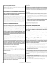
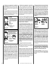
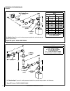
TRAHCHTGNELNOITCESTNEV
noitceSlanimoN
)sehcni(htgneL
6 21 42 63 84
T
O
T
A
L
Q
T
Y
noitceSteN
)sehcni(htgneL
2/1-4 2/1-01 2/1-22 2/1-43 2/1-64
tneVfothgieH snoitceStneVforebmuN
sehcni tf
441 21 1 0 0 0 3 4
051 5.21 0 1 0 0 3 4
5.451 578.21 1 1 0 0 3 5
5.061 573.31 0 2 0 0 3 5
5.271 573.41 0 0 0 5 0 5
771 57.41 1 0 0 5 0 6
381 52.51 0 1 0 5 0 6
681 5.51 0 0 0 0 4 4
5.091 578.51 1 0 0 0 4 5
5.691 573.61 0 1 0 0 4 5
5.502 521.71 0 1 1 5 0 7
702 52.71 0 0 0 6 0 6
5.112 526.71 1 0 0 6 0 7
5.712 521.81 0 1 0 6 0 7
5.922 521.91 0 0 1 6 0 7
5.232 573.91 0 0 0 0 5 5
732 57.91 1 0 0 0 5 6
5.142 521.02 0 0 0 7 0 7
642 5.02 1 0 0 7 0 8
252 12 0 1 0 7 0 8
462 22 0 0 1 7 0 8
672 32 0 0 0 8 0 8
972 52.32 0 0 0 0 6 6
5.082 573.32 1 0 0 8 0 9
5.382 526.32 1 0 0 0 6 7
5.982 521.42 0 1 0 0 6 7
5.103 521.52 0 0 1 0 6 7
5.013 578.52 0 0 0 9 0 9
513 5.62 1 0 0 9 0 01
5.523 521.72 0 0 0 0 7 7
033 5.72 1 0 0 0 7 8
633 82 0 1 0 0 7 8
543 57.82 0 0 0 01 0 01
5.943 521.92 1 0 0 01 0 11
273 13 0 0 0 0 8 8
5.673 573.13 1 0 0 0 8 9
5.973 526.13 0 0 0 11 0 11
5.814 578.43 0 0 0 0 9 9
324 52.53 1 0 0 0 9 01
564 57.83 0 0 0 0 01 01
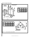
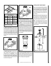
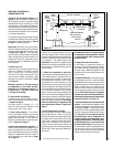
13” Min.
(330 mm)
13” Min.
(330 mm)
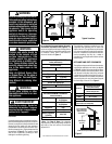
Figure 14
Vertical (Offset) Installation
Analyze the vent routing and determine the
quantities of vent sections and number of elbows
required. Refer to Vertical Vent Figures and
Tables on Pages 13 and 14 to select the type
of vertical installation desired. Vent sections
are available in net lengths of 4-1/2" (114 mm),
10-1/2" (267 mm), 22-1/2" (572 mm), 34-1/2"
(876 mm) and 46-1/2" (1181 mm). Refer to the
Vent Section Length Chart on this Page for an
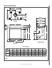
aid in selecting length combinations. Elbows are
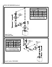
available in 90° and 45° configurations. Refer to
Figure 17 on Page 12 for the SV8 E45 and SV8
E90 elbow dimensional specifications.
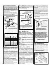
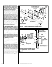
Where required, a telescopic vent section
(SV8LA) may be used to provide the installer
with an option in installing in tight and con-
fined spaces or where the vent run made up
of fixed length pieces develops a joint in a
undesirable location, or will not build up to the
required length. The SV8LA Telescopic Vent
Section has an effective length of from 1-1/2"
(38 mm) to 6-3/4" (171 mm). The SV8LA is
fitted with a dimpled end (identical to a normal
vent section component) and a plain end with
3 pilot holes. Slip the dimpled end over the
locking channel end of a standard SV8 vent
component the required distance and secure
with three screws.
Maintain a minimum 1" (25 mm) clearance
to combustible materials for all vertical ele-
ments. Clearances for all horizontal elements
are 3" (76 mm) on top, 1" (25 mm) on sides
and 1" (25 mm) on the bottom.
A. Frame ceiling opening - Use a plumb line
from the ceiling above the appliance to locate
center of the vertical run. Cut and/or frame
an opening, 13" x 13" (330 mm x 330 mm)
inside dimensions, about this center mark
(Figure 14).