


7
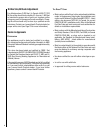
NOTE: DIAGRAMS & ILLUSTRATIONS ARE NOT TO SCALE.
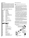
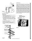
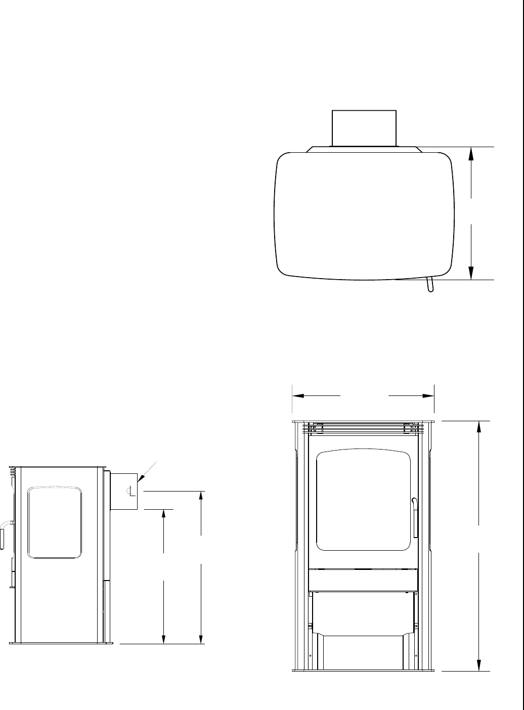
14-7/8”
(378mm)
18-1/2”
(470mm)
32-1/2”
(826mm)
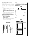
rear vent dimensions
Flue Collar
24-3/4”
(629mm)
28”
(711mm)
dimensions
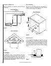
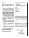
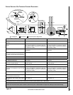
The gas line attaches to the gas valve at the back of the stove
2-1/2” in from the left side of the stove and 8-1/2” up from
the base of the unit. Test all gas connections for leaks with
a gas leak test solution.
preparing your vision™ stove for installation
Read all instructions before beginning your installation. If
instructions have not been read carefully, your installation
could void your warranty and may create a serious fire,
health, or other safety hazard.
The Lennox Hearth Products warranty will be voided if one
of the following occurs:
• Installation of any damaged stove or vent system
component.
• Unauthorized modification of the direct vent system.
• Installation other than as instructed by Lennox Hearth
Products, Security™ Chimneys, or Simpson Dura-
Vent.
• Installation of any stove or vent system component not
manufactured or approved by Lennox Hearth Products,
Security™ Chimneys, or Simpson Dura-Vent.
When planning the installation for your Vision gas stove, it’s
necessary to consider the following:
• Where the unit is to be installed
• The vent system configuration to be used
• Gas supply (NG or LP)
• Electrical wiring
• Optional accessories (door trim/grill assembly and
wall-mounted or remote thermostat)
top view
front view
Figure 1
Figure 2
Figure 3