


16
NOTE: DIAGRAMS & ILLUSTRATIONS ARE NOT TO SCALE.
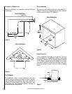
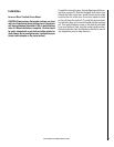
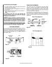
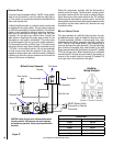
Gas Line Installation
This stove must be connected to the gas line in accordance
with local codes and/or the National Fuel Gas Code, ANSI
Z223.1 (In Canada, the current CAN/CSA B149.1 installation
code). The gas line screws into the gas valve at the back
of the stove 2-1/2” in from the left side of the stove and 8-
1/2”up from the base of the unit. After connecting the gas
line, all joints in the line and connections at the valve should
be checked for leaks.. After connecting the gas line, all joints
in the line and connections at the valve should be checked
for leaks using a gas leak test solution.
gas pressure requirements
A MAJOR CAUSE OF OPERATING PROBLEMS WITH GAS
APPLIANCES IS IMPROPER GAS PRESSURE!
The most important item to check during the initial
installation and the first thing to check when operating
problems occur is gas pressure! This appliance will
not function properly unless the required gas pressure
is supplied. See the table on this page for gas pressure
requirements.
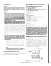
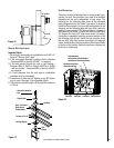
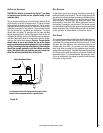
Two pressure taps are provided on the stove’s valve to check
gas pressures. To access the taps, remove the two socket
head screws from the valve control panel. The taps are
located below the on/off/pilot knob. The left tap is the inlet
(supply) pressure side. To check inlet pressure (with the stove
burning) insert a small flat-bladed screwdriver into the tap
and turn a half-turn counter-clockwise. Cover the tap with
the line from the manometer and check the pressure. Close
the tap gently but securely after completing the check. The
manifold (outlet) tap is to the right of the inlet tap. To check
manifold pressure (with the stove burning at the high burn
setting) insert a small flat-bladed screwdriver into the tap
and turn a half-turn counter-clockwise. Cover the tap with
the line from the manometer and check the pressure. Again,
close the tap gently but securely after completing the check.
Check the taps for gas leaks with a gas leak test solution
(retighten if necessary).
If the pressure is not sufficient, make sure the gas supply line
is large enough, the supply regulator improperly adjusted,
and the total gas load for the residence does not exceed the
amount supplied.
The appliance and its individual shut off valve must be
disconnected from the gas supply piping system during
any pressure testing of that system at test pressures in
excess of 1/2 psig.
The appliance must be isolated from the gas supply piping
system by closing its individual manual shut-off valve
during any pressure testing of the gas supply piping system
at test pressures equal to or less than 1/2 psig. Check
with your gas supplier or plumber.
lp and natural gas supplies
Your Vision™ gas stove is equipped from the factory for
use with natural gas only as specified on the Safety / Listing
label attached to the appliance. This appliance can only be
operated using propane gas (LP) if a certified fuel conver
-
sion kit provided by Lennox Hearth Products is installed by
a qualified service technician.
Also check the orifice size on the label on the igniter bracket.
It must be the correct size for the fuel and altitude.
Do not run propane tank dry. Running the tank dry may
cause a hazardous condition due to pressure drop in
empty tank.
Solid fuel is NOT to be used with this unit.
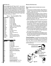
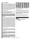
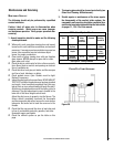
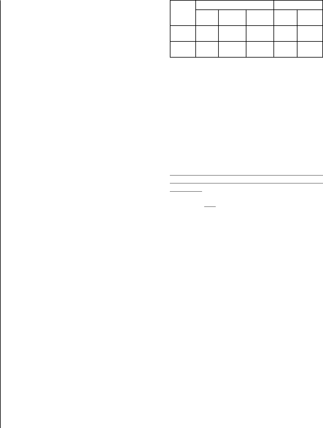
Fuel
Type
Inlet Pressure Manifold Pressure
Desired Minimum Maximum On Hi
Fire
On Lo
Fire
Natural
Gas
7" WC 5" WC 10.5" WC 3.5" WC 1.8" WC
LP Gas 11" WC 11" WC 13" WC 10" WC 6.0” WC