


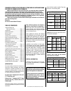
NOTE: DIAGRAMS & ILLUSTRATIONS ARE NOT TO SCALE
4
IMPORTANT
Keep your house well ventilated
during the curing process. The
odor and haze emitted by the
curing process can be quite
noticeable and may set off a
smoke detector.
Lighting Millivolt Appliances
To light millivolt appliances refer to the detailed
lighting instructions found on
Page 16 (Eng-
lish) and
Page 17 (French). Millivolt appliance
lighting instructions may also be found on the
pull-out lighting instruction labels located in the
control compartment (below glass door).
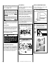
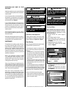
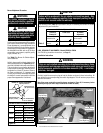
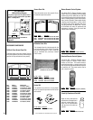
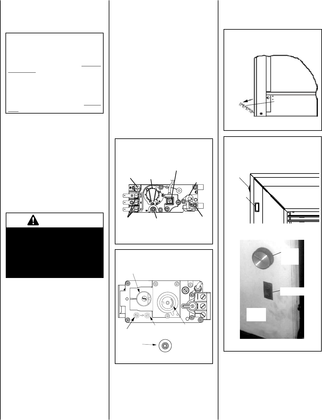
Figure 4
Burner On/Off Switch and Rheostat Location
If optional surround is installed
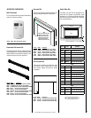
Control Compartment Access
Pull down hinged door to access control compartment
Pull down lower
louver (hinged)
Side View of Insert
Figure 3
Burner On/Off
Switch
Rheostat
(blower
speed
control)
Left Front
surround
Panel
Units with Beveled Surround
Units with Flat Surround
Left Front
surround
Panel
Rheostat
(blower
speed
control)
Burner On/Off
Switch
CONTROL COMPARTMENT ACCESS
Pull down hinged door to access control
compartment
(see Figure 3).
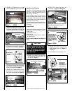
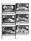
Test gauge connections are provided on the
front of the millivolt gas control valve (identi
-
fied IN for the inlet and OUT for the manifold
side). See
Figures 1 & 2.
This appliance must not be connected to a
chimney or flue serving a separate solid-fuel
appliance.
Burn-in Period
During the first few burns of these appliances
there will be some odor due to the curing of the
high temperature paint and burning off of lubri
-
cants used in the manufacturing process.
Depending on your use, the burn-in period may
take a few hours or a few days.
Do not turn on
blower during Burn-In period.
GAS CONTROLS
See Figure 3, showing how to access the
control compartment.
These millivolt appliances are fitted with a burner
ON/OFF Switch, located on the side surround
panel as shown in
Figure 4 on Page 4. Once
the pilot is lit, and valve knob is in the ON posi
-
tion, the ON/OFF switch will control the appliance
ON/OFF operation. To operate, toggle the switch
between its ON and OFF positions.
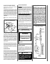
Variable Flame Height Adjustment
These millivolt appliances are equipped with a
variable gas control valve. Flame height may be
adjusted through a range between fixed low and
high settings by rotating the HI/LO knob on the
valve (see Figures 1 & 2) alternately, while the
appliances are in operation.
O
N
O
F
F
P
I
L
O
T
L
O
H
I
Figure 1
GAS CONTROL
KNOB
INLET
PRESSURE
TAP
PILOT
ADJUSTMENT
SCREW
WIRING
TERM-
INALS
OUTLET
PRESSURE
TAP
TP/TH
PIEZO
IGNITER
TH
TP
H
I
L
O
W
TPTH TP TH
P
I
L
O
T
P
I
L
O
T
O
N
it
O
F
F
IN
OUT
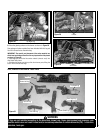
Figure 2
MODEL EDVI25
SIT Millivolt Gas Valve Controls
MODELS: EDVI30 & EDVI35
Honeywell Millivolt Gas Valve Controls
CONVERTIBLE
HI/LO REGULATOR
(adjusts flame height
and heat output)
GAS CONTROL
KNOB
INLET
PRESSURE
TAP
OUTLET
PRESSURE
TAP
CONVERTIBLE
HI/LO REGULATOR
(adjusts flame height
and heat output)
PIEZO
IGNITER
This appliance must be isolated from the
gas supply piping system (by closing its
individual manual shut-off valve) during
any pressure testing of the gas supply
piping system at test pressures
equal to
or less than 1/2 psig (3.5 kPa).
This appliance and its individual shut-off
valve
must be disconnected from the gas
supply piping system during any pressure
testing of that system at pressures
greater
than 1/2 psig (3.5 kPa).