


3
NOTE: DIAGRAMS & ILLUSTRATIONS ARE NOT TO SCALE
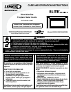
INTRODUCTION
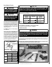
The Insert models covered in this manual are
Direct-Vent sealed combustion gas heaters
designed for residential application for install
ion into an existing masonry or factory built
solid-fuel fireplace. The required liners for the
air intake and exhaust are as follows:
Air Intake: Use 3” diameter UL 1181 or UL
1777 listed liner only.
Exhaust: Use 3” diameter UL1777 listed
gas vent liner only. DO NOT USE UL 1181
LISTED LINER.
These vent systems must be routed through
the existing fireplace flue system to the vent
termination.
These millivolt appliances are designed to
operate on either natural or propane gas. A
millivolt gas control valve with piezo ignition
system provides safe, efficient operation.
External electrical power is required to operate
the air circulation blower.
These appliances comply with National
Safety Standards and are tested and listed
by OMNI-Test Laboratories Inc.; Beaverton,
Oregon (see report numbers on cover) to
ANSI Z21.88 (in Canada, CSA-2.33), and
CAN/CGA-2.17-M91 in both USA and Canada,
as vented gas heaters.
Installation must conform to local codes.
In the absence of local codes, installation
must comply with the current National Fuel
Gas Code, ANSI Z223.1 / NFPA 54 - latest
edition. (In Canada, the current CAN-1 B149
installation code.) Electrical wiring must
comply with the National Electrical Code
ANSI/ NFPA 70 - latest edition. In Canada,
the current CSA C22-1 Canadian Electrical
Code - latest edition.
GENERAL INFORMATION
Installation, repair and annual service inspec-
tion should be performed by a qualified
service technician.
TABLE OF CONTENTS
Important Safety and
Warning Information ....................
Page 2
Introduction ......................................Page 3
General Information ..........................
Page 3
Burn-In Period ..................................
Page 4
Gas Controls .....................................
Page 4
Variable Flame Adjustment ................
Page 4
Control Compartment Access ...........
Page 4
Operation/Care of Your Appliance .....
Page 5
Maintenance ......................................Page 5
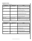
Maintenance Schedule ......................
Page 7
Front Glass Enclosure Panel,
Removal and Installation .................
Page 8
Burner Adjustments ..........................
Page 8
Flame Appearance and Sooting .........
Page 8
Log/Rockwool/Vermiculite Placement
Page 9
Millivolt Appliance Checkout .............
Page 13
Blower Operation ..............................
Page 13
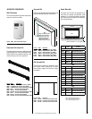
Fireplace Requirements .....................
Page 13
Wiring Diagrams ...............................
Page 13
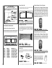
Accessory Components ....................
Page 14
Lighting Instructions – Millivolt ........
Page 16
Replacement Parts List .....................
Page 18
Troubleshooting Guide – Millivolt
......Page 20
Product Reference Information .........
Page 24
CONGRATULATIONS ON THE PURCHASE OF YOUR NEW GAS APPLIANCE MANU-
FACTURED BY LENNOX HEARTH PRODUCTS.
When you purchased your new gas-fired heater, you joined the ranks of thousands
of individuals whose answer to their home heating needs reflects their concern for
efficiency and our environment. We extend our continued support to help you achieve
the maximum benefit and enjoyment available from your new gas-fired heater. It is our
goal at Lennox Hearth Products to provide you, our valued customer, with an appliance
that will ensure years of trouble-free warmth and pleasure.
Thank you for selecting a Lennox Hearth Products gas-fired heater as the answer to
your home heating needs.
Sincerely,
All of us at Lennox Hearth Products
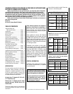
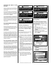
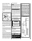
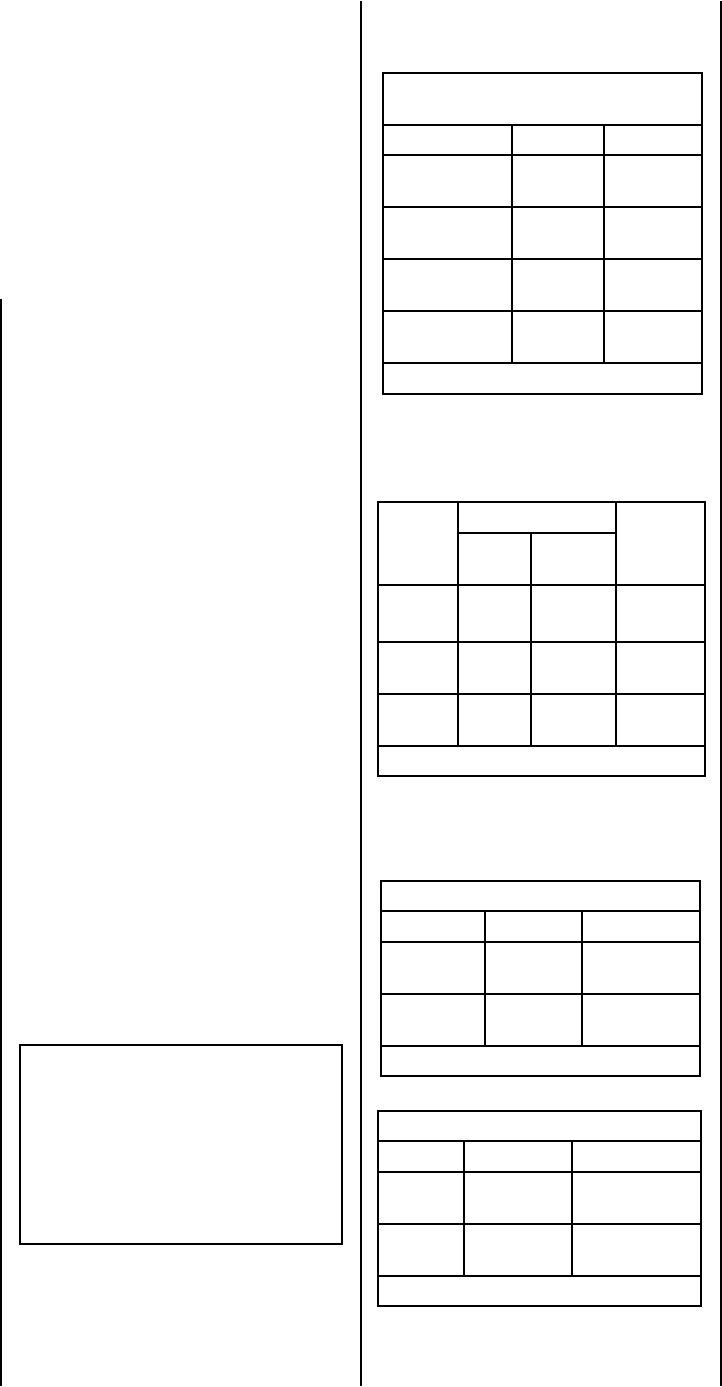
Millivolt Models with
MAnnually-Modulated Gas Valves
Nat. Gas Propane
Model No. Input Rate
(BTU/HR)
Input Rate
(BTU/HR)
EDVI25
17,000 to
25,000
19,000 to
25,000
EDVI30 21,500 to
30,000
22,000 to
28,000
EDVI35 25,500 to
35,000
26,000 to
34,000
Table 1
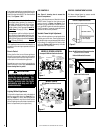
It is imperative that the control compart-
ment, burners and circulating air passage
ways of the appliance be kept clean.
S'assurer que le brùleur et le compartiment
des commandes sont propres. Voir les
instructions d'installation et d'utilisation
qui accompagnent l'appareil.
Input of millivolt models is variable. These rates
are shown in the following table:
Table 2 shows the units' gas orifice size for
the elevations indicated.
Model
No.
Orifice Size Elevation
Feet
(meters)
Nat.
Gas
Prop.
Gas
EDVI25
#41
(.096”)
#53
(.0595”)
0-4500
(0-1372)
EDVI30 #37
(.104”)
1/16”
(.0625”)
0-4500
(0-1372)
EDVI35 #33
(.113”)
#51
(.067”)
0-4500
(0-1372)
Table 2
Tables 3 and 4 show the gas pressure
requirements for all models:
Inlet Gas Supply Pressure (all models)
Fuel # Minimum Maximum
Natural Gas 4.5" WC
(1.12 kPa)
10.5" WC
(2.61 kPa)
Propane 11.0" WC
(2.73 kPa)
13.0" WC
(3.23 kPa)
Table 3
Manifold Gas Supply Pressure (all models)
Fuel # Low High
Natural
Gas
(Lo) 1.6" WC
(.40 kPa)
(Hi) 3.5" WC
(.87 kPa)
Propane (Lo) 6.3" WC
(1.57 kPa)
(Hi) 10.0" WC
(2.49 kPa)
Table 4