


NOTE: DIAGRAMS & ILLUSTRATIONS ARE NOT TO SCALE
13
To light the burner, rotate the gas valve
control knob counterclockwise to the “ON”
position then turn “ON” the on/off switch To
light the burner, rotate the gas valve control
knob counterclockwise to the “ON” position
then turn “ON” the on/off switch mounted
on the surround assembly (see
Figure 4
on Page 4) or operate the burner with the
optional remote control, wall thermostat or
control switch.
With proper care and maintenance, your appli-
ance will provide many years of enjoyment. If
you should experience any problem, first refer
to the troubleshooting guide in this manual. If
problem persists, contact your Lennox Hearth
Products Dealer.
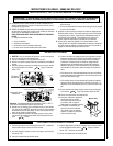
BLOWER OPERATION
When the insert heats up, the blower will automat
-
ically be turned on by the fan disc located under
the firebox bottom on the front left side. It will
come on at the speed determined by the rheostat
located on the side surround panel (see Figure
4 on Page 4). To adjust the blower speed, dial
the rheostat to the desired speed setting. Rotate
the dial down (clockwise), just past the click (the
first ON position) for the highest speed setting.
Turning the knob further clockwise will provide
slower blower speeds. Note: If the rheostat is not
turned “on,” the blower will not operate.
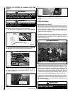
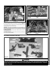
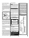
Proper Pilot Flame Appearance
MILLIVOLT APPLIANCE CHECKOUT
Light the pilot by following the instructions
Pages 16 or 17 of this manual.
The pilot flame should be steady, not lifting
or floating. Flame should be blue in color with
traces of orange at the outer edge. The top 3/8"
(10 mm) at the pilot generator (thermopile)
and the top 1/8" minimum (tip) of the quick
drop out thermocouple should be engulfed
in the pilot flame. The flame should project 1"
(25 mm) beyond the hood at all three ports
(Figure 38).
Replace logs if removed for pilot inspec
-
tion.
Figure 38
¹⁄₈" Min
(3 mm)
Thermocouple
Igniter Rod
Hood
³⁄₈" Min
(9 mm)
Thermopile
Pilot
Nozzels
FIREPLACE REQUIREMENTS
IMPORTANT: When installing these appliances
into a factory built fireplaces or heatforms, the
air flow within and around the fireplace shall not
be altered by the installation of the insert (i.e.
DO NOT BLOCK louvers or cooling air inlet or
outlet ports, circulating air chambers in a steel
fireplace liner or metal heat circulator).
CAUTION: The factory built firebox must
accept the insert without modification other
than removing bolted or screwed together
pieces such as smoke shelf/deflectors, ash lips,
screen or door tracks, log grates, refractory and
damper assemblies. Any fireplace component,
which is removed, must be retained so they
can be reinstalled to restore the fireplace to
its original operating condition. The removal
of any part must not alter the integrity of the
outer shell of the pre-engineered fireplace
cabinet in any way.
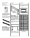
If any components are removed from (or altered)
from the existing fireplace, a Warning Label (see
Figure 39) must be affixed inside the fireplace
firebox, so that it shall be visible upon removal of
the fireplace insert. Note: RTV high temperature
silicone is an approved adhesive.
Figure 39
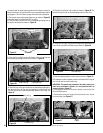
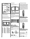
WIRING DIAGRAMS
Wiring diagrams are provided here for refer-
ence purposes only. This information is also
provided on schematics attached directly to the
appliance on a pullout panel located within the
control compartment.
IMPORTANT: Blower ground wire with
power cord green wire should be attached
to the ground screw. Failure to do so will
result in a potential safety hazard. The
appliance must be electrically grounded
in accordance with local codes or, in
the absence of local codes, the National
Electrical Code, ANSI/NFPA 70 - latest
edition. (In Canada, the current CSA C22-1
Canadian Electrical Code - latest edition.
WARNING: THE POWER CORD MUST BE
PLUGGED DIRECTLY INTO A PROPERLY
GROUNDED THREE-PRONG 120 VOLT,
60 HZ WALL RECEPTACLE. DO NOT CUT
OR REMOVE THE GROUNDING PRONG
FROM THIS PLUG. DO NOT ROUTE
POWER CORD UNDER OR IN FRONT OF
APPLIANCE.
Room Air Circulation Blower
Figure 40
Fan Disc
Rheostat
Blower
Assembly
Power Cord
Black
Hot (Live)
RedBlackBlack
Black
120 V AC
Blower Wiring Diagram
White
(Neutral)
Green
(Ground)
CAUTION
Label all wires prior to discon-
nection when servicing con-
trols. Wiring errors can cause
improper and dangerous appli-
ance operation.
Fireplace Warning Label
(Provided in Accessory Package)
WARNING
THIS FIREPLACE HAS BEEN ALTERED TO
ACCOMMODATE A FIREPLACE INSERT
AND SHOULD BE INSPECTED BY A QUALI-
FIED PERSON PRIOR TO RE-USE AS A
CONVENTIONAL FIREPLACE.