


7
After having selected the final mounting position of the appliance, taking
into account the site requirements as specified in Section 8 of these instruc-
tions, the integrity of the wall, and the feasibility of the proposed supply
pipe routing, the firebox of appliance may be secured to the wall.
To ensure customer safety, be sure to design the installation so that the
strength of both the wall and any wall fixings used are sufficient. Lennox
Hearth Products assumes absolutely no responsibility for injuries and
damages that may occur due to improper installation or handling.
The appliance should not be installed until all dry wall sanding and wall
painting has been completed.
10.0 MOUNTING THE APPLIANCE
Non-concealed gas connections may be made using the entry points
on the base of the firebox. A concealed gas connection may be made
using the knockout hole in the center back of the firebox. Select the most
appropriate entry point and knock out the relevant hole.
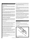
If a concealed gas connection is to be made, the supply pipe should always
be sleeved through walls and floors using the shortest possible route.
For concealed supply pipe routing, pipes must (where possible) be ver-
tical and providing there is sufficient wall thickness available, they should
be placed in pipe chases. Horizontal pipe runs should be avoided where
possible. Prior to chasing a solid wall, an inspection should be made
to note the proximity of any cables/sockets outlets which may already
be buried. Pipes must be secured using suitable clips and protected
against corrosion. Ideally factory finished protected pipe-work and fittings
should be used. Joints should be kept to a minimum and compression
fittings must not be used. The pipe-work installation must be tested for
soundness before any protection is applied and/or the pipe-work and
fittings are buried.
WARNING
The wall where the appliance is to be installed must
be capable of long-term support of the total load of
the appliance. Measures should also be taken to
ensure sufficient strength to withstand the force of
earthquakes, vibration and other external forces.
Incorrect installation can cause the appliance to fall from the wall and
cause injury. Do not block the ventilation holes of the appliance. The
wall onto which the appliance is installed must be flat. Install only on a
vertical surface. Avoid sloped surfaces. Installation onto anything other
than a vertical wall may result in fire, damage or injury.
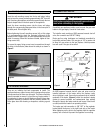
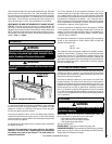
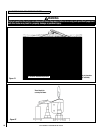
A full size fitting template is supplied to assist with wall mounting.
Mark the positions shown as “Fixing Points” on the wall. If the appli-
ance is to be mounted on the inner leaf of a conventional cavity wall, or
a solid wall, drill four holes using a 1/4” masonry bit. Insert the fiber
wall plugs provided.
If the appliance is to be mounted on a dry lined wall or a timber framed
construction wall then special cavity screw fixings will be required which
are not supplied with this product. These should be constructed from
metal and not plastic.
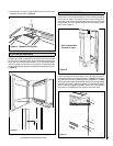
If a concealed gas connection is to be made ensure the gas supply pipe
is in it’s final position and can enter the appliance in the correct position
when the appliance is hung on the wall.
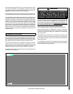
Figure 2
NOTE: DIAGRAMS & ILLUSTRATIONS ARE NOT TO SCALE