6
8.0 SITE REQUIREMENTS
This appliance is designed to be wall-hung. Do not recess any part of
the appliance into the wall.
This appliance may be installed in any room in a home except bedrooms
or bathrooms - or areas where large amounts of steam are likely to be
generated.
It should be noted that heaters create warm air currents. These currents
move heat to wall surfaces next to the heater. Installing the heater next
to vinyl or cloth wall coverings or operating the heater where impuri-
ties in the air (such as tobacco smoke or candle smoke) exist, may
discolor walls.
Installation in living rooms is common, however other rooms such as
kitchens, dining rooms and hallways are permitted, providing a suitable
natural gas supply is available, and rooms sizing and ventilation require-
ments are strictly adhered to (see Section 7.0).
The appliance is designed to be versatile, and as such will operate correctly
when exposed to normal gentle drafts experienced within the home. It
is not recommended, however that the appliance be installed in areas
where it is likely to be exposed to persistent strong drafts, that may be
generated by outside doors or windows, air vents etc. It is recommended
that the appliance should not be installed within 20” of any air vent.
CLEARANCES TO NON-COMBUSTIBLES
Non-combustible surfaces are defined as brick, metal, marble, concrete
etc. and also a number of man-made materials impervious to flame. If in
doubt refer to the material manufacturer for further information before
proceeding with installation.
Clearances to the sides of the appliance are 4”. Clearance to the front
of the appliance is 20”.
The back of the appliance may be installed directly onto a non-combustible
wall, providing the area behind the appliance is flat and does not interfere
with the various vent holes in the back panel of the appliance.
The appliance may be installed with or without a non-combustible hearth.
If a hearth is fitted, the size and design may be as desired.
A non-combustible shelf of any depth may be positioned above the appli-
ance provided it is no closer than 16” from the top of the appliance glass
panel and the wall above the appliance is non combustible.
CLEARANCES TO COMBUSTIBLE MATERIALS
Combustible materials are defined as wood, fabrics, or other materials
likely to combust if exposed to flame. Generally, any material, which is
likely to discolor, melt or misshape when exposed to moderate heat,
should be considered as a combustible material or surface.
Clearance to the sides of the appliance are 4” but curtains, drapes and
other fabrics are not permitted within a distance of 20” of the appliance
sides. No such materials are permitted directly above the appliance
regardless of distance.
The minimum clearance to the ceiling above the appliance is 32” measured
from the top of the appliance glass panel.
Combustible materials should not be positioned directly in front of the
appliance within a distance of 40”.
Under no circumstances should any electrical equipment e.g. plasma
screen TV sets etc. be positioned on the wall above the appliance. The
appliance is designed to be wall mounted alone and not in conjunction
with any type of combustible fire surround.
No combustible shelves should be positioned on the wall above the
appliance.
It should be established that any mirrors or picture frames etc. to
be positioned on the wall above the appliance are able to withstand
prolonged exposure to moderate heat and moisture before proceeding
with their installation.
The wall must be structurally sound and constructed from a material
capable of withstanding moderate heat. Finished plaster, conventional
wall paper and dry-lined plasterboard are examples of suitable materi-
als. Materials such as flock, blown vinyl and embossed paper which are
sensitive to even small amounts of heat should be avoided as scorching
and or discoloration may occur over time.
If the appliance is to be mounted on a dry-lined wall or a timber framed
construction wall then the integrity and ability of the wall to carry the
weight of the appliance must be confirmed. It is important in these
circumstances that any vapor control barrier is not damaged, and that
any structural members of the house frame are not damaged.
The appliance may be positioned as close to a solid floor (i.e. stone,
wooden laminate etc.) as the particular design of fire frame permits,
however it is not permitted to install the appliance within 4” of carpet,
rugs or fabric materials of any kind. This dimension is measured verti-
cally to the bottom of the appliance frame.
9.0 PREPARING THE APPLIANCE
Follow the steps below:
Gas connection: The heater gas inlet connection is 3/8” NPT at the
regulator, located below the burner, in the center of the heater.
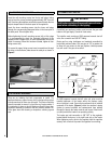
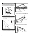
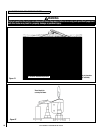
There are four possible entry points for the gas supply pipe-work to
enter the appliance firebox. These entry points are ‘knock out’ type holes
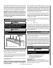
(shown in Figure 1).
Figure 1 - Gas Supply Entry Points
NOTE: DIAGRAMS & ILLUSTRATIONS ARE NOT TO SCALE


