


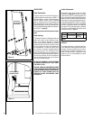

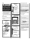
1. Combustible material must be installed flush
with the fireplace. It may not project in front
of and on the fireplace (i.e. the steel facade
of the fireplace) (see Figure 19).
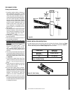
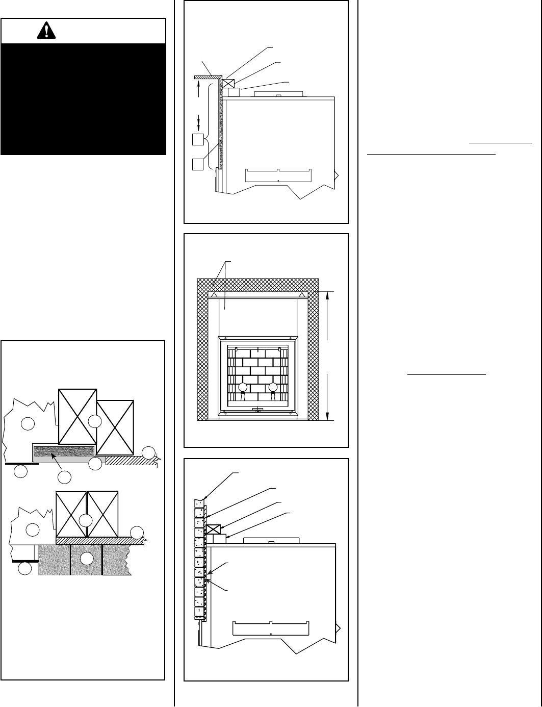
2. Non-combustible materials such as brick,
stone or ceramic tile may project in front
of and onto the fireplace facing (see Figure
20).
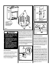
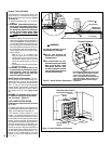
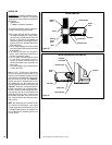
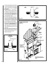
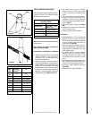
MANTEL AND FACING
The mantel must be installed at least 59”
(1500 mm) above the base of the fireplace
(see Figure 18).
IMPORTANT
The facade must be removable
once installed. The facade is
designed to overlap any facing
material installed on the front of
the fireplace. If thicker material
is installed, use the facade as a
template and make sure it can be
easily removed for servicing.
FACING
1
3
4
5
6
2
1
2
7
3
4
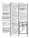
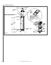
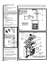
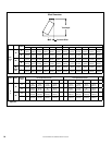
1. Fireplace
2. Front of fireplace
3. Wood frame (2” x 3” min)
4. Drywall
5. Tiles
6. Rock board or other
7. Brick
Fireplace Frame Section
(Top View)
Figure 17
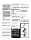
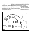
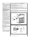
Optional Fireplace Blower (UZY5)
A heat activated blower is sold as an option. It is
designed to be located in the back of the fireplace
and increase the air flow around the firebox. It
uses regular 120V and must be connected to the
main electrical circuit by a qualified electrician.
An electrical box must be installed outside the
fireplace.
WARNING: Because of the fireplace size and
obstructive air venting, we don’t recommend
the installation of the blower unless the gravity
ducting is installed on the fireplace.
If you wish to adjust the blower speed, an optional
variable speed control (VRUW) can be installed
in line with the wiring. Again, use a qualified
electrician for installation.
To install the blower,
1- Remove the refractory bricks and the and
-
iron.
2- Remove the metal plates covering the bottom
and back of the hearth firebox.
3- Disconnect the main electric cable from the
blowers by unplugging its two quick connec-
tors.
4- Remove the knock-out in the front right side
of the fireplace outer casing.
5- Install a
metallic wire protector and slide the
blower main electrical cable from the outside
to the inside of the unit.
6- Install the two blowers in the back of the
fireplace through the holes in the back.
Warning: Make sure there are no contact
between the blowers and the door slider.
7- Reconnect the main cable quick connectors
and stick (magnet) the heat activate switch
under the right side of the firebox. Using
aluminum tape, make sure no wiring touch
the firebox by taping it to the bottom of the
fireplace panel.
8- Install all plates, bricks and andiron.
9- Connect the blower plug into the electrical
box located outside the fireplace.
Flameproof Facing
Figure 19
Figure 18
}
}
}
Drywall
2” x 3” Min.
Spacer
Mantel
59”
u
u
Non-Combustible
Panel Only
v
Flameproof Facing
v
Mantel and Facing
(Side View)
Drywall
2” X 3” Min.
Spacer
Metal Mesh Screwed in
Board and Fireplace
Non-Combustible Panel Only
Figure 20
Only non-combustible mate-
rial should be superposed or
projecting over the front of the
fireplace.
59”
Min.
NOTE: DIAGRAMS & ILLUSTRATIONS ARE NOT TO SCALE.
13