


27
• Air Wash
A small slot in the door that allows room air to be pulled into the
firebox and pours over the inside surface of the door glass to inhibit
the build up of soot.
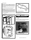
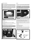
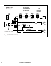
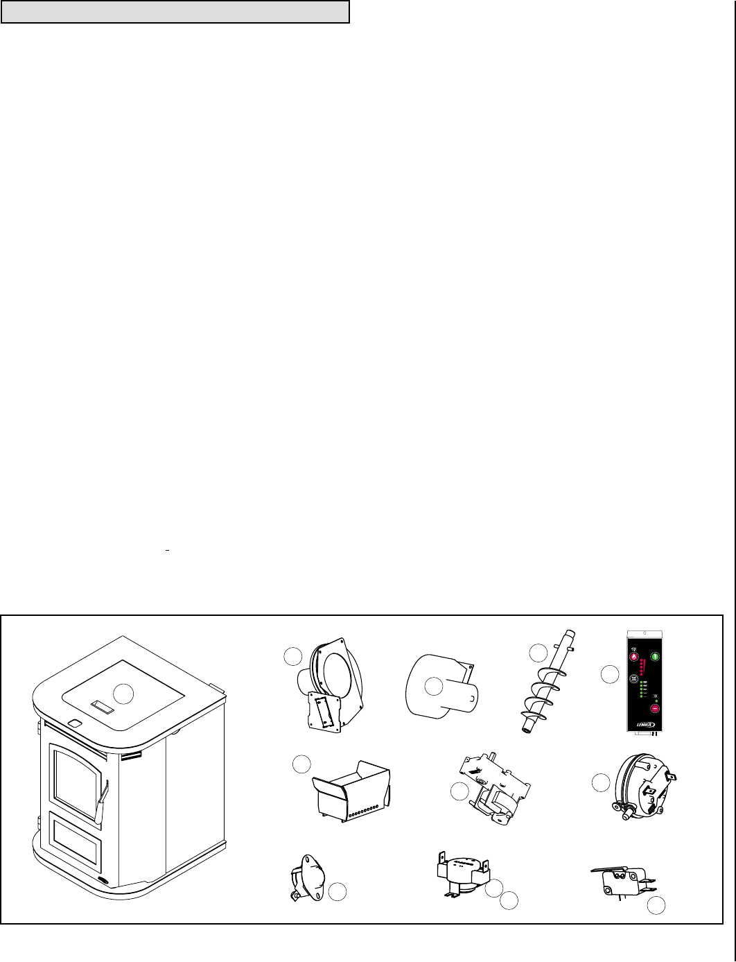
• Auger (A)
A motor powered screw device that transfers the fuel from the hopper
to the feed chute to deliver pellets to the UltraGrate™.
• Auger Motor (B)
It drives the auger. Motor specifications are: 0.5 Amp, 1.25 RPM
(revolutions per minute).
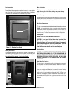
• Blower, Convection (Room Air) (C)
The blower function is to transfer the heat from the appliance to heat
the room air.
• Blower, Combustion (Exhaust) (D)
It has a radial impeller to deliver more air to the UltraGrate™. It pulls
air into the UltraGrate by creating a negative pressure. This is done
by extracting the exhaust gases out of the firebox and pushing the
exhaust downstream to the flue exit.
• Thermal Switches, High Limit
There are two of these high-limit thermal switches on this model. If
a temperature reaches the high limit temperature, the reset switch
will “trip” and stop the flow of electricity to the auger motor. The
thermal switches will not reset until they have cooled below low reset
temperature).
- Auto Reset Thermal Snap Switch for Room Air Blower (L250-30F,
N/C*) (E)– This switch will trip at 250° F and will automatically
reset when it reaches a temperature of 220° F. This switch is
located on the room air blower jacket and is designed to detect
an overfire condition.
-
Auto Reset Thermal Snap Switch for Combustion Air Inlet
(L250-30F, N/C*) (F)
This switch will trip at 250° F and will
automatically reset when it reaches a temperature of 220° F.
This switch is designed to detect reversed flow or excessive
heat in the ashpan area. This switch is located on the firebox
base behind the convection jacket, directly above the ashpan.
This switch is most easily accessed by removing the ashpan
• Thermal Switch, Low Limit (Ceramic, F140-20F, N/O*) (G)- This "proof
of fire" switch will close at 140° F and will not open until it reaches
a temperature of 120° F. This switch is located on the combustion
blower (behind the right side panel). It is designed to shut down the
stove (auger motor and both blowers) if it does not detect the heat of
a fire at the end of the initial startup period.
• Hopper Lid Switch (H)
It is located on the left hinge area inside the hopper. It detects whether
the hopper lid is open and will turn off the auger motor if the hopper
lid is not properly closed. When opening the hopper when refueling,
do not allow the hopper lid to remain open too long or the fire may
extinguish. NEVER DISCONNECT OR BYPASS THIS SWITCH FOR
ANY REASON.
• Hopper (I)
The hopper is where the pellets are stored.
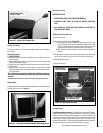
• Control Board (Heat Output Button) (J)
It controls power to the feed system - auger motor and combustion
blower. Use the heat output button to adjust to any of the five feed
rate settings (which controls the burn rate).
• Pressure Switch (K)
A safety device used to shut off the feed system (auger motor) if there
is too much back pressure in venting system. Some possible causes
are as follows:
-
The venting system is obstructed.
-
High altitude or other misc. environmental conditions affecting
exhaust flow.
-
Improper venting system.
The Pressure Switch is located inside the right access door right next
to the combustion blower.
• UltraGrate (Burn Grate) (L)
This is where combustion occurs and may be referred to as the “Burn
Grate”.
* N/C = Normally Closed
N/O = Normally Open
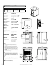
COMPONENT DEFINITIONS
NOTE: DIAGRAMS & ILLUSTRATIONS ARE NOT TO SCALE
START
HEAT
OUTPUT
BLOWER
FEEDING
STOP
(-) (+)
O
(-) (+)
O
COMBUSTION
AIR
PELLET
FEED
HEART H PRO DUCT S
A
B
C
D
E
F
G
H
I
J
K
L
Figure 35