


18
Control Board Operation
START BUTTON
The "START" Button turns on the pellet stove.
If the exhaust does not reach operating tempera-
ture within 30 minutes, the stove will automati-
cally shut down. The pellet stove can be restarted
by pushing the "START" Button again.
RESTART
AUGER ON (green LED) - The auger restarts and
returns to delivering fuel to the UltraGrate™.
STOP BUTTON
Note: The "START" Button has to be activated to
give power to the AUGER ON/OFF button.
The "STOP" button turns the pellet stove OFF.
When the LED is green, the auger is ON.
SHUT DOWN (LED off) - Auger turns OFF and
fuel delivery stops. The blowers will continue to
operate until the stove has cooled sufficiently.
Stove enters shut down mode.
HEAT OUTPUT BUTTON
When not using a wall thermostat, the "HEAT
OUTPUT" button provides the ability to burn
at five separate settings from low (#1) to high
(#5). The "HEAT OUTPUT" button regulates the
fuel feed setting and the combustion air supply
simultaneously.
Each time the "HEAT OUTPUT" button is pressed
the heat output will advance to a higher setting.
When at the highest setting (#5), if the button
is pressed again it will go back to the lowest
setting. Settings can be changed at any time
but will only take affect after the start-up cycle
is complete.
CONVECTION (ROOM AIR) BLOWER
BUTTON
The "BLOWER" button operates the convection
blower. This will change the flow of hot air into
the room. Five settings are available from low
(#1) to high (#5). When the "BLOWER" button
is pressed, the green indicator light will scroll
from low to high. When at the highest setting
(#5), if the button is pressed again it will go
back to the lowest setting.
When the "HEAT OUTPUT" button is on position
#5, the lowest blower setting is #3. When the
heat output button is on position #4, the lowest
blower setting #2. This is a safety precaution
to protect against overheating. Blower settings
can be changed at any time, but will only take
affect after the start-up cycle is complete.
Note: The control board has an internal memory
which recalls the last setting prior to loss of
power.
IMPORTANT NOTE:
If the fuel feed trim or combustion air trim needs to be adjusted, contact
your dealer or qualified technician to calibrate internal software. The trim controls should
only be adjusted for the proper flame if all other options did not achieve proper adjustment.
It is recommended that the damper be used to fine-tune your stove to your particular fuel and
installation configuration (see Damper Adjustment on Page 9 and Damper Adjustment Guide
-
lines on Page 20).
WARNINGS
Never empty pellets from the Burn-Pot into the hopper. Pellets that
may appear to be cool may retain enough heat to ignite other pellets
resulting in smoke or fire damage.
DO NOT OVERFIRE THIS STOVE. This may cause serious damage to
your stove and void your warranty. It also may create a fire hazard in
your home. IF ANY EXTERNAL PART OF THE UNIT BEGINS TO GLOW,
YOU ARE OVERFIRING. Immediately press the “STOP” button on the
control board.
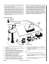
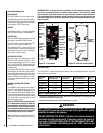
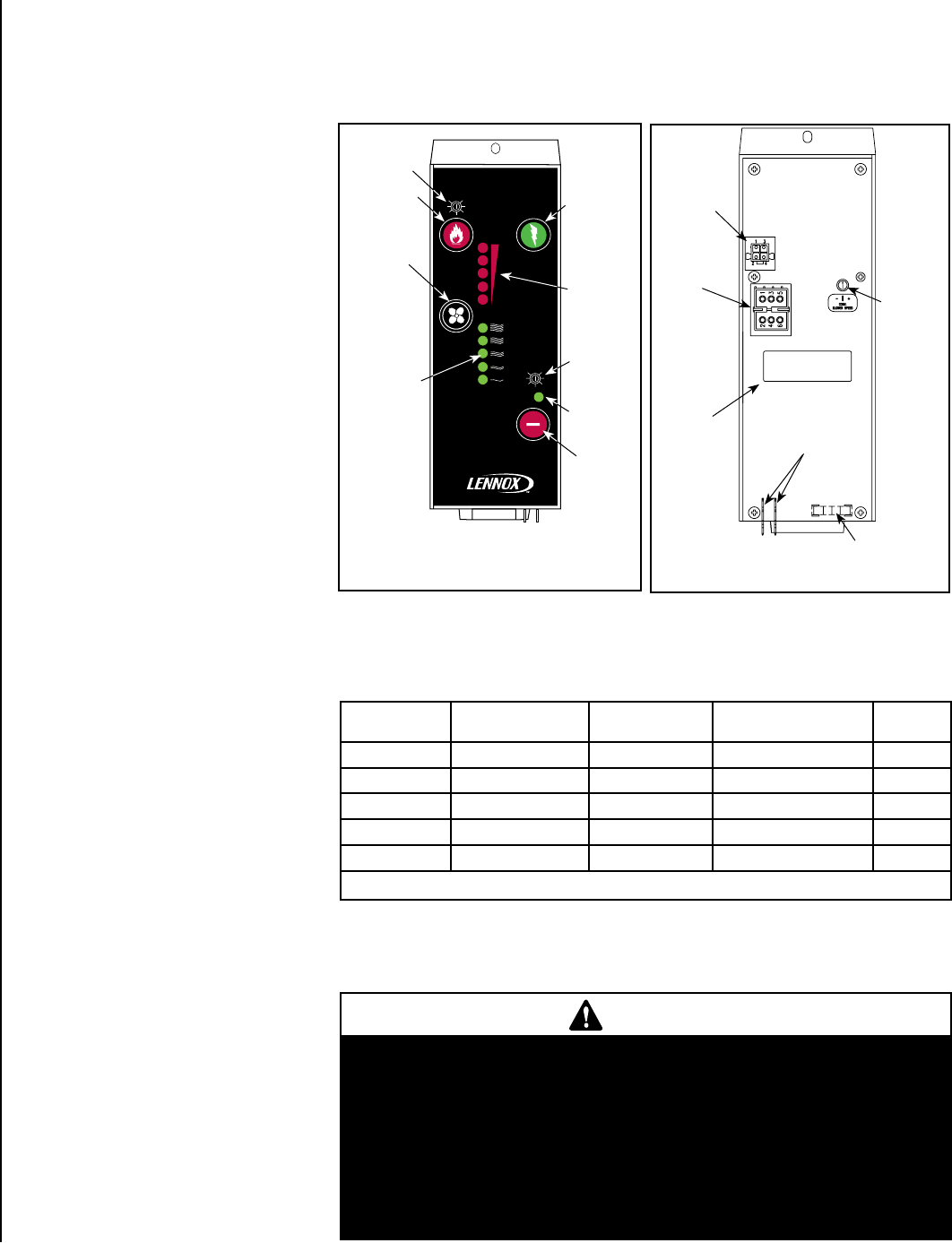
NOTE: DIAGRAMS & ILLUSTRATIONS ARE NOT TO SCALE
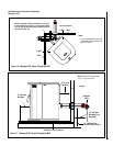
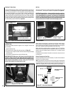
Fuse
To Thermostat
Terminal
Convection
Blower
Speed Trim
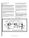
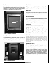
Figure 22 - Control Board
Figure 23 - Back Side of Control Board
Main
Wire
Harness
Connector
P/N
Label
Location
4 Position
Connector
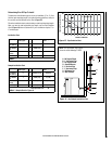
Fuel Delivery Rate
The "HEAT OUTPUT" button manages the fuel delivery rate by controlling the amount of time the
auger motor will run as follows:
* Feed rates are approximations only. Actual feed rate will vary depending on size, quality and length
of fuel used and variations in line voltage.
w Estimated heat input based on fuel value of 8400 BTU per lb. of fuel.
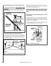
START
HEAT
OUTPUT
BLOWER
FEEDING
STOP
(-) (+)
O
(-) (+)
O
COMBUSTION
AIR
PELLET
FEED
HEARTH PRODUCTS
Convection
(room air)
Blower LEDs
- Green
(5 places)
Combustion
Blower Trim
Start
Button
m 5 - High
m 4 - Med. High
m 3 - Medium
m 2 - Med. Low
m 1 - Low
Heat Output
Button
Convection
(room air)
Blower
Button
Stop
Button
Heat Output
LEDs - Red
(5 places)
Auger LED
Green = On
Heat Output
Setting
Auger Motor OFF/ON
Time (seconds)
* Lb.’s Per Hour
Fuel Delivery
w Approximate BTU Per
Hour Fuel Delivery
Burn Time
(hours)
(#5) High =
1.3 / 0.9 3.8 Lb.'s /hr. 32,000 BTU/hr 15
(#4) Med.High =
1.8 / 0.9 3.0 Lb.'s /hr. 25,000 BTU/hr 18
(#3) Med.=
2.2 / 0.9 2.5 Lb.'s /hr. 21,000 BTU/hr 22
(#2) Med.Low =
2.6 / 0.9 2.0 Lb.'s /hr. 17,000 BTU/hr 31
(#1) Low =
3.1 / 0.9 1.5 Lb.’s hr. 13,000 BTU/hr 37
Table 5 - Model Montage™ 32FS Note: Maximum hopper capacity is 55 lb.’s
Pellet Feed
Trim Pot