


10
VENTING REQUIREMENTS
It is recommended that only an Lennox Hearth Products dealer install your
pellet stove. The specified installation requirements must be followed to
ensure conformity with both the safety listing of the appliance and local
building codes. All clearances, installation instructions and precautions
specified by the vent manufacturer must be followed.
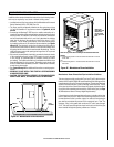
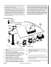
Selecting a Location
Review the appliance clearance requirements before installing the
venting system (see Page 5). Position the appliance far enough away
from walls to allow adequate room for servicing. Choose the appliance
location with the least amount of interference with the house framing,
plumbing, wiring, etc.
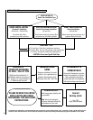
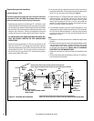
Preferred Vent Configuration
For the best performance, we recommend a vent run design which runs
vertically and terminates above the roof line. This design will allow natural
draft to improve the flow of flue gases and will aid in combustion and
stove performance.
Note: 30 feet maximum vertical vent allowed (6 inches minimum verti-
cal).
Type of Pipe
This stove is approved for venting with Type L and Type PL pellet vent
pipe (sometimes referred to as “L-Vent pellet vent”, listed to UL 641 or
ULC S609). We recommend the use of venting products manufactured by
Security Chimneys International. Connect the pellet vent pipe or the “tee”
to the flue collar using a minimum of three screws and seal as specified
in “Pipe/Liner Joint Requirements” on this Page. Do not use class B
gas chimney or single wall chimney as a substitute.
Size of Pipe
These pellet stoves are approved for use with the following vent sizes: 3”
(75 mm) standard, or 4” (100 mm), see Page 13 - for determining correct
size vent). When 4” pipe is used: for horizontal vent installations use a 3”
(75 mm) to 4” (100 mm) adapter - available from vent manufacturer. For
vertical installations use a 3” (75 mm) to 4” (100 mm) “tee” - available
from vent manufacturer.
Offsets
In every installation, a single or double clean-out “tee” is recommended
for every ninety-degree offset (this tee will help collect ash residue and
will allow for routine cleaning without the need to disconnect sections
of pipe).
Pipe Clearances/Requirements
See pipe manufacturers instructions for installation of venting components
and clearances. Follow pipe manufacturers installation precautions for
passing pipe through a combustible wall or ceiling (i.e. use an approved
thimble).
Notes
• Offsets and horizontal runs accumulate fly-ash and soot which reduces
the exhaust flow and performance of the stove.
• Total Offsets in venting system should not exceed 270° total in direc
-
tion change.
• Maximum Vertical Vent - 30 feet (9.14 M)
• Horizontal Runs - The maximum total horizontal run must not exceed
10 feet (3.1 meters).
• Horizontal run of pipe requires 1/4” (7 mm) rise per foot.
• Pellet vent pipe requires 3” (75 mm) clearance from outside of pipe
unless otherwise specified by vent manufacturer - all diameters: 3” (75
mm) and 4” (100 mm). A support bracket must be installed every 4
feet (1.2 m) of pellet vent pipe on the exterior wall of the house unless
otherwise specified by vent manufacturer.
• It is not recommended to terminate exhaust vent on the prevailing wind
side of the house.
• In Canada, where the venting may pass through a wall, or partition of
combustible materials, the installation shall conform to CAN/CSA-B365.
When installing the wall thimble and other venting components, follow
the vent manufacturers instructions. Maintain an effective vapor barrier
at the location where the chimney or other component penetrates to
the exterior of the structure.
Pipe/Liner Joint Requirements
Silicone sealant and three screws are required to secure the first vent con-
nection to the appliance flue collar. Seal the remaining vent sections per
the vent manufacturers instructions and secure all sections with 3 screws
minimum per section. ALL horizontal joints must be sealed gas-tight (air
tight, sealed connection). Use RTV high temperature silicone or Interam,
if necessary, to provide a complete seal between vent sections.
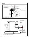
Connection to Masonry Chimney through a Wall
Be sure to verify the construction of a masonry chimney, as it may have
combustible framing.
Approved liner when relining Masonry or Factory-Built Fireplaces is
2100HT (degree F.) liner listed to UL 1777 or ULC S635.
Connection to an Existing Class A Chimney
A chimney adapter can be used to make the connection from 3” (75
mm) or 4” (100 mm) pellet vent pipe (listed to UL 641 or ULC S609) to
existing UL chimney system. Verify with the pipe manufacturer that your
pipe brands will interconnect.
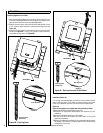
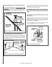
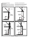
Horizontal Vent Installations
On all horizontal vent installations (short, horizontal runs with no vertical
pipe); care should be taken when choosing a location for terminating the
vent. It is not recommended to directly vent the exhaust on the prevail-
ing wind side of the house. It is recommended that when an appliance
is vented directly through a wall, a minimum of 8 feet (2.5 m) of vertical
pipe should be installed to create some natural draft. This will reduce
the possibility of smoke or odor entering the dwelling during appliance
shutdown or loss of power.
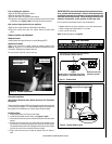
Vent Termination
Do not terminate vent in an enclosed or semi-enclosed area such as:
carports, garage, attic, crawl space, under a deck, porch, narrow walkway,
closely fenced area, or any location that can build up a concentration of
fumes such as a stairwell, covered breezeway etc.
Vent surfaces can get hot enough to cause burns if touched. Adults
should supervise children when they are in the area of a hot stove.
Non-combustible shielding or guards may be required.
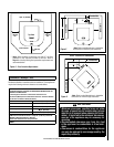
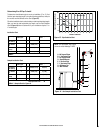
Termination Cap
The termination of the outside chimney of the pellet stove shall be located
in accordance with the following:
A. Higher than 3 feet (.92 m) above any forced air inlet (air conditioner,
etc.) located within 10 feet (3 m).