


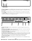
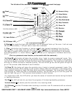
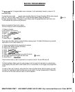
CONTROLLER SECTION
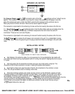
7.) Master
IR
Output
-
this connector allows the “party” mode to apply to multiple units if additional
units are added.
8.) Master IR Input
-
this is for the “party” mode controller. This controller should be located near
the unit and sources. It will override all zone controllers and select a source which will then play in
all zones. This mode is used for playing the same background music in all zones such as during a
party. The individual wall controllers still have the ability to select a different source after the party
mode is engaged. It uses a standard 8 pin RJ-45 connector.
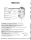
9.)
Individual Zone
#I
Controller
-
this connector hooks up the wall controllers used in zone
#I.
The signals from this wall controller control all the functions in zone
#I.
It uses a standard 8-pin
RJ-
45 connector.
This connector is duplicated for the remaining 5 zones and function exactly the same.
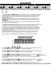
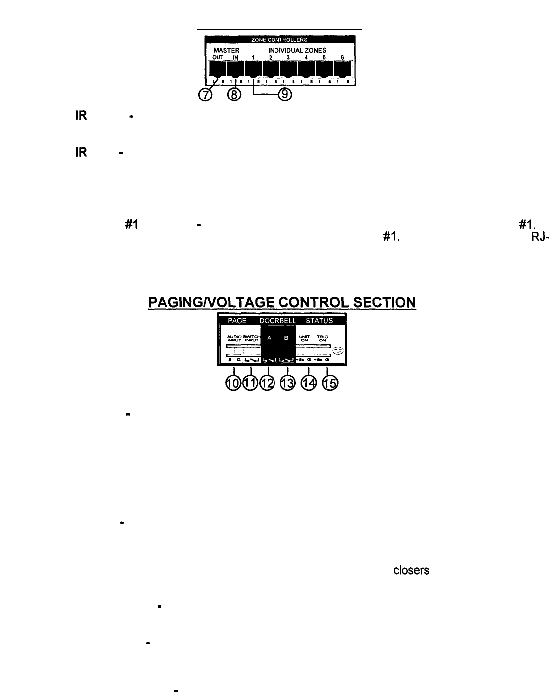
10.) Audio Inputs
-
this is an audio sensing circuit and accepts the signal from an external phone
system or a pre-amplified microphone (i.e.: a mixer output), that has the capability of sending a page
signal from the master phone unit. The signal from this phone system will mute whatever source is
playing in all zones and allow the person speaking to page into all zones simultaneously and make
their announcement. When the signal is disengaged, the music will return to the previous level. Even
zones that are not currently on will “open” and allow the announcement to be made. Inside the unit
is a master DIP type switch which allow the installer to turn off the paging and doorbell override. This
is especially suited for a nursery. Pin 1 is for signal and pin 2 is for ground.
11.) Switch Inputs
-
this input is designed for older systems like intercoms that require a push to talk
“latch” mode contact before the audio signal can pass through. This is a “hard” bypass of the audio
sources. This can act as a whole house mute as well.
12.) Front Doorbell Input -this input takes the signal from the contact
closers
from the front doorbell
transformer. When engaged, the source signal mutes and a distinctive chime (on board) plays through
the speakers, It will even play through zone speakers that aren’t on unless locked out.
13.)
Back Doorbell Input
-
same as above but with a separate distinctive chime sound so you can
differentiate between the doors.
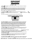
14.) Control Voltage In
-
this allows an external sub system that sends a control voltage output to
this system to power up the unit from the “sleep” mode. This signal can be from 5 to 12 volts D.C.
The front panel power switch must be on for this to work.
15.) Control Voltage Output
-
this output sends a constant 5 volt D.C. signal out to trigger ancillary
equipment when the unit is powered up. When the unit goes into the “sleep” mode, this voltage stops.
Page
4
SMARTHOME.COM™ 1-800-SMART-HOME 949-221-9200 http://www.smarthome.com Order #8270C