


SECTION 5 SERVlCER'STECH.I..ORMATION
5A. TROUBLESHOOTING
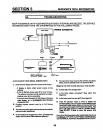
AUTOMATIC ELECTRONIC DIAGNOSTICS
The face plate computer has a self-diagnostic
function for the electrical system (except input
power and water meter). The Erlr" I
computer monitorsthe electron- D-_
ic components and circuits for
correct operation. If a malfunction occurs, an
error code appears in the face plate display.
The chart below shows the errorcodes thatcould
appear, and the possible defects for each code.
While an error code appears in the display, all
face plate buttons are inoperable except the
SELECT button. The SELECT button remains
operational so the service person can make the
MANUAL INITIATE ELECTRONIC DIAGNOS-
TICS to further isolate the defect, and check the
water meter.
POSSIBLE DEFECT
CODE MOST LIKELY _ _ LESS LIKELY
Err 01 motor inop. / widncj hamass or connection to switch / position switch / face plate
Err 02 face plate
Err 03 motor inop. / face plate
Err 04 face plate / position switch
Err 05 face plate
PROCEDURE FOR REMOVING ERROR CODE FROM FACE PLATE: 1. Unplug transformer 2. Correct defect
3. Plug-in transformer 4. Wait for 6 minutes. The error code will retum ifthe defect was not corrected.
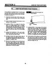
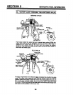
MANUAL INITIATED ELECTRONICS DIAG-
NOSTICS
1. To enter diagnostics, press and hold the
SELECT button until (000 - -) shows in the
display.
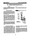
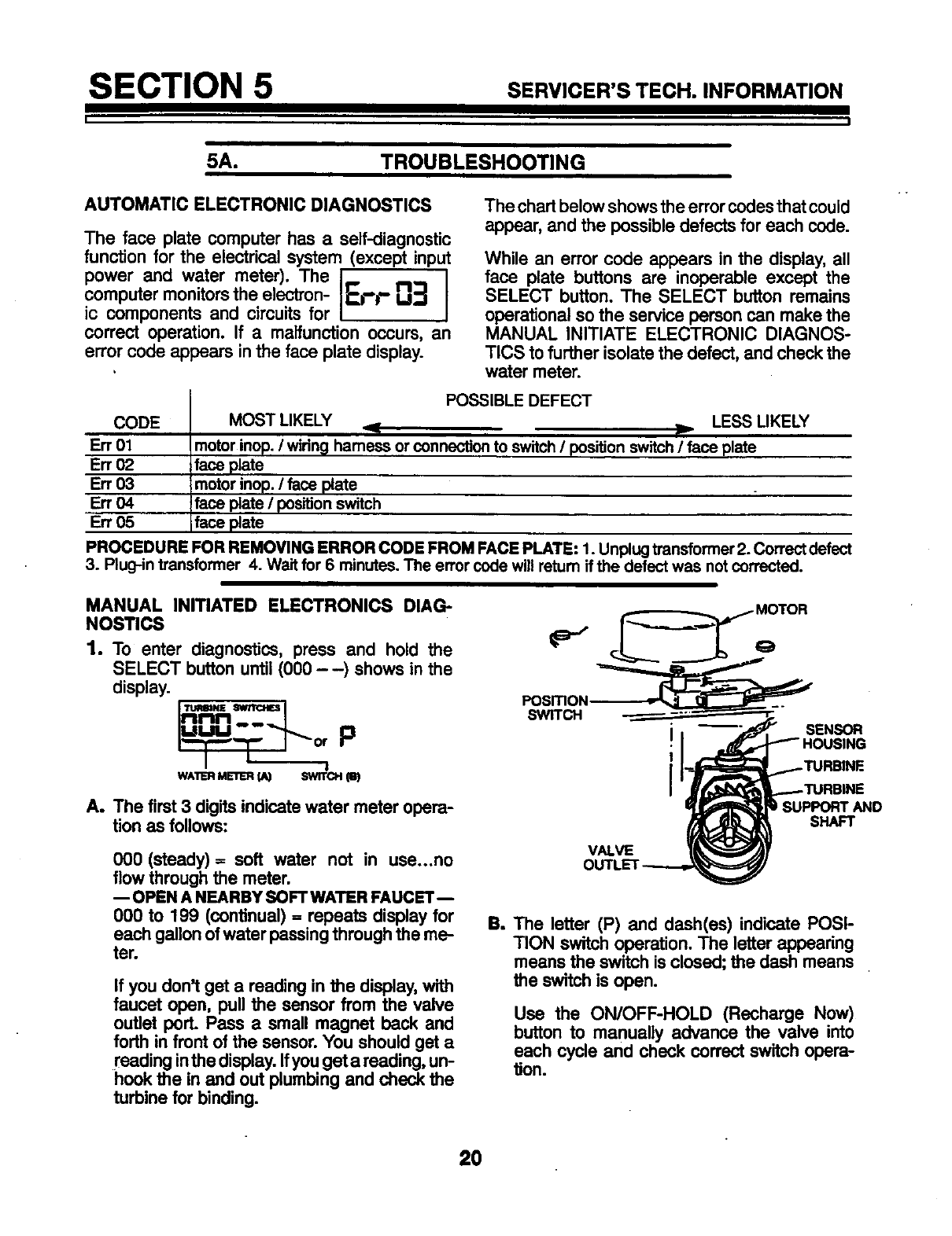
_ MOTOR
PosmoN
""'plnnn___"l swn'c.
!1
i .._._td_'_....,.--.-'I'URB|NE
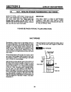
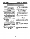
A. tionTheasfirstfollows:3digits indicate water meter opera- _ S%P_AND
000 (steady)= soft water not in use...no VALVE It_k_A)'
flow through the meter. OUTLET----.--,_/
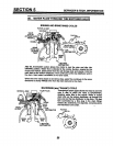
--OPEN A NEARBY SOFTWATER FAUCET-
000 to 199 (continual) = repeats display for
each gallon ofwater passingthrough the me-
ter.
B. The letter (P) and dash(as) indicate POSI-
TION switch operation. The letter appearing
means the switch isclosed; the dash means
the switch is open.
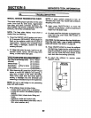
Use the ON/OFF-HOLD (Recharge Now)
button to manually advance the valve into
each cycle and check correct switch opera-
_on.
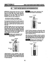
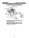
If you don't get a reading in the display, with
faucet open, pull the sensor from the valve
outlet porL Pass a small magnet back and
forth in front of the sensor. You should get a
reading inthedisplay. Ifyouget a reading, un-
hook the in and out plumbing and check the
turbine for binding.
20