


[i!i !!:;:_!! :;:_!!:;:_!! : SECTION 5 SERVICE TECH. INFORMATION
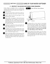
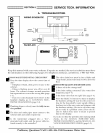
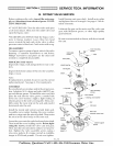
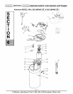
B. ROTARY VALVE SERVICE
Before working on the valve, turn off the water sup-
ply and disconnect from electrical power. TO RE-
LIEVE PRESSURE:
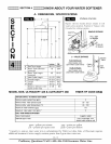
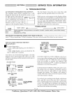
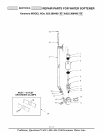
Install bearing onto gear shaft. Install motor plate
and tighten screws to a snug fit. See page 6- 3 for de-
tailed schematic.
• 3 VALVE BYPASS: Close the inlet valve and open
a soft water faucet. Then close the outlet valve and
open the bypass valve.
• SEARS SPECIAL BYPASS: Slide the bypass valve
stem to bypass position. Loosen three hex head
screws toward the back side of the valve to allow
pressure water to bleed out. Catch water with a rag.
Lubricate the gear on the motor, and the valve cam
gear with Molykote grease, or other high quality
gear lubricant.
Be sure to orient switch as shown, with lever toward
the cam.
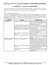
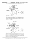
DISASSEMBLY
To remove a part or group of parts, refer to the valve
drawing. A common screwdriver or nut driver,
Phillips screwdriver and pliers are the only tools
needed to completely disassemble.
SERVICING THE VALVE
Inspect all o-rings, seals and gaskets for wear or de-
fects.
Inspect the bottom surface of the rotor for scratches,
chips or wear.
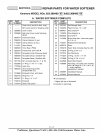
Note:
If replacement is needed, be sure to use the current
replacement part. See page 6- 3 for repair parts.
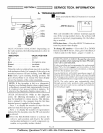
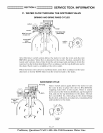
ASSEMBLY
Be sure all parts are in place and in the proper posi-
tion. Lubricate ALL o-rings and seals with FDA ap-
proved silicone grease. To install the rotor seal, first
place the seal into the valve groove, rounded side
down (see cross-section). Apply a light coating of
silicone grease to the seal's crossing ribs. Then, care-
fully center the wear strip on the seal, and push it
downward onto the seal.
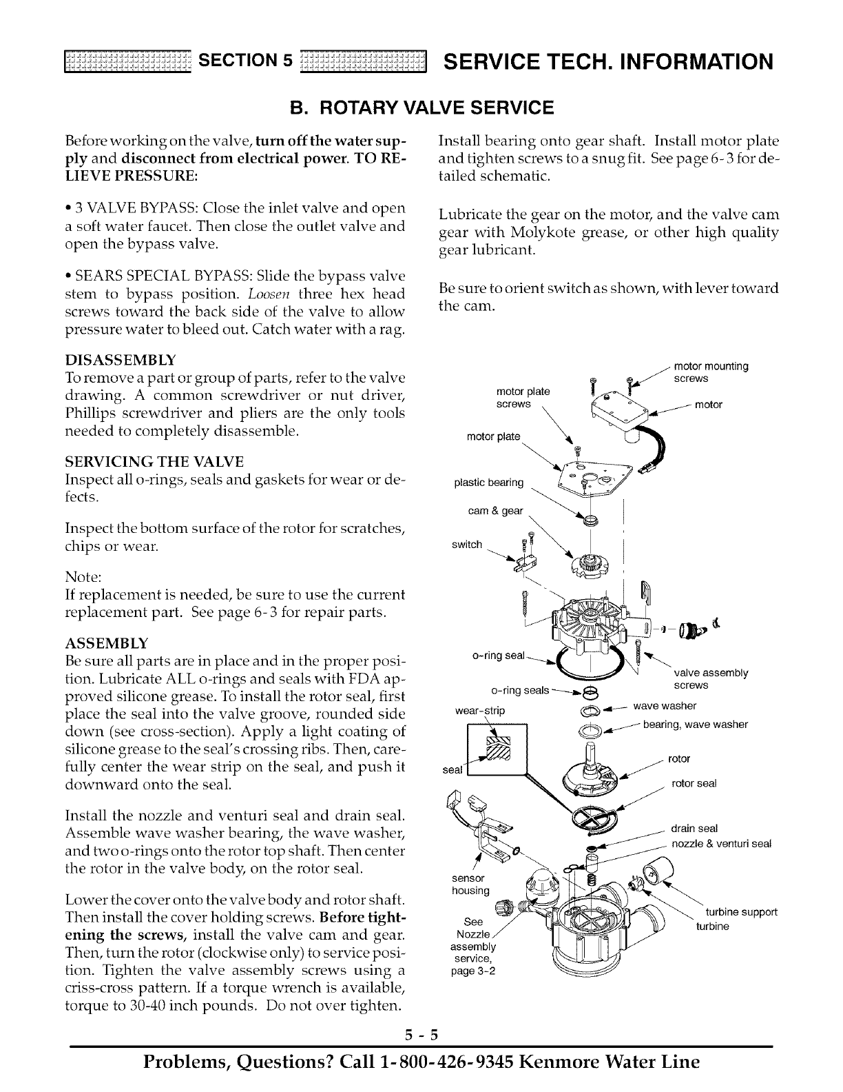
motor plate
screws
motor plate _
plastic bearing
cam & gear
motor mounting
screws
//motor
switch
seal"
rotor
)_'''/ rotor seal
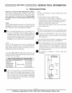
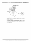
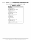
Install the nozzle and venturi seal and drain seal.
Assemble wave washer bearing, the wave washer,
and two o-rings onto the rotor top shaft. Then center
the rotor in the valve body, on the rotor seal.
Lower the cover onto the valve body and rotor shaft.
Then install the cover holding screws. Before tight-
ening the screws, install the valve cam and gear.
Then, turn the rotor (clockwise only) to service posi-
tion. Tighten the valve assembly screws using a
criss-cross pattern. If a torque wrench is available,
torque to 30-40 inch pounds. Do not over tighten.
sensor
housing
See
Nozzle
assembly
service,
page 3-2
/ drain seal
_.dt// nozzle & venturi seal
5-5
Problems, Questions? Call 1- 800- 426- 9345 Kenmore Water Line