


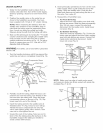
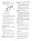

WATER SUPPLY
1. Water for the humidifier must be taken from a
nearby cold water line. Turn off the water supply.
Drain by opening a faucet at a lower level of the
line.
2. Position the saddle valve on the water line as
close to the humidifier as possible. You have
been supplied with 10 feet of 1/4" plastic tubing.
NOTE: When measuring the distance from the
saddle valve location to the humidifier, keep in
mind that the tubing must be supported; there-
fore, it must run along the ceiling and walls.
Measure along the path that the tubing wiii follow.
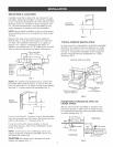
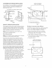
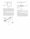
3. Back out the piercing pin by turning the "T" handle
counter clockwise and clamping the saddle valve
body securely on the water line with a rubber
gasket positioned as shown in Fig. 19. On galva-
nized or copper pipe over 5/8", first drill a 5/32"
diameter hole in the pipe.
WARNING: For safety, use a hand drill or grounded
electric drill.
4. Turn the handle clockwise until it has pierced the
water line and valve is completely closed (Fig. 19).
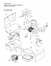
Brass Compression Sleeve
_[ _ xf Brass insert
j Hand
8.
Close previously opened fauceL Turn on the main
water supply, Place a pail under the end of the
tubing, Open the saddle valve. Flush the line.
Make sure there are no leaks along the line or at
the valve, Turn valve off.
9. Reassembiy of humidifier case.
a. For Front Servicing:
Attach the lower case making sure both side
latches are secure. Slide the reservoir assembly
(Fig. 20) into case, connect the electrical
disconnect for the media motor. Install lower
rod screw (Fig. 9).
b.
For Bottom Servicing:
Place the reservoir assembly (Fig. 20) into the
lower case and attach the lower case, making
sure both side latches are secure. Connect the
media motor electrical disconnect. Install
lower rod screw (Fig. 9)
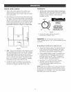
Media Motor
and Panel
Wheel
Panel Clip
Divider
Brass
Compression
Nut
Rubber
Gasket
(Stem Up)
Water Pipe
Fig, 19
5. Partially uncoil the tubing. Slide the brass com-
pression nut over the tubing. The threads in the
nut must face the tubing end. Place the brass
compression sleeve as shown in (Fig. 19). Slip
brass insert into end of the tubing.
6. Insert the tubing end into the saddle valve at
threaded stem "A" (Fig. 19) as far as it wiii go.
Thread the brass compression nut onto the
valve, then tighten gently with a wrench. Take
care not to over-tighten the nuL
7. Unwind the rest of the tubing. Take care not to
kink it. Run the tubing along fiat surfaces to the
humidifier. Support the tubing as needed to
avoid contact with furnace.
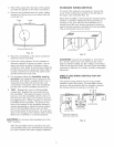
Overflow
Reservoir
Fig, 20
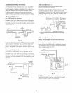
NOTE: Make sure top edge of media motor panel
and reservoir divider are firmly seated with panel clip
installed (Fig. 21 & 22).
Fig, 21
10