


38
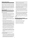
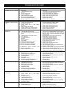
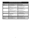
Has the thermal switch
tripped?
NO
Check for insufficient
combustion air.
Are there openings
for make-up air to
enter the room?
Are the openings of sufficient size?
See “Combustion Air Supply and Ventilation”
section in this manual for requirements.
Is there a furnace/air
handler in the same room as
the water heater?
Does the return air duct for the furnace/air handler draw
its air from a separate location than the water heater?
See the “Location Requirements” and “Combustion Air
Supply and Ventilation” sections in this manual.
Is there proper drafting at the
draft hood? See “Checking the
Draft” section in this manual.
Is the flame-arrestor free from
debris due to excessive lint, dirt,
dust or oil?
Check the water heater for a Flammable Vapor (FV) event. Note: it may be
necessary to remove the manifold door assembly to visually inspect the water
heater. Reference the “Maintenance of your Water Heater” section of this
manual for removal instructions.
Is the igniter wire insulation burnt or
show signs of discoloration?
Install correct size make-up air openings per
the “Combustion Air Supply and Ventilation”
section in this manual.
NO
NO
Correct size of openings to
allow sufficient air.
Refer to the “Maintenance of Your Water Heater” section of this
manual for information on cleaning the flame-arrestor.
NO
NO
Check the vent system for restrictions/obstructions and check the vent
termination height. Refer to the “Installation Instructions” section of this
manual for specific requirements.
NO
Is the pilot tube
damaged?
NO
Does the flame
arrestor show signs
of discoloration and/
or debris?
Shut-off the gas supply to the water
heater at the manual gas shut-off
valve, then contact Sears Service at
1-800-4-MY-HOME (1-800-469-4663).
YES
YES
YES
YES
YES
YES
YES
YES
YES
NO
Contact a local Heating, Ventilation, Air
Conditioning & Refrigeration authorized
service provider.
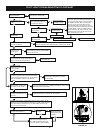
Does pilot light go out when
button is released?
YES
NO
Check Draft. (See “Checking the
Draft” section of this manual.)
NO
YES
Is the thermocouple
connection loose?
Tighten the connection
NO
Test the thermocouple using the following
procedure: Disconnect the thermocouple from the
gas control valve/thermostat. Using a multimeter
with alligator clip leads, attach the red lead to
the body (copper part) of the thermocouple.
Attach the black lead to the end (silver part) of
the thermocouple that connects to the gas control
valve/thermostat. Follow the instruction to light
the pilot and watch the voltage readings on the
multimeter. After 45 seconds the meter should
read 12 millivolts DC or more.
NO
Does the thermocouple pass the test?
YES
YES
YES
Are the wires from the gas
control valve/thermostat firmly
connected to the switch?
NO
Are the wires damaged
and/or frayed?
YES
NO
Secure connections
and attempt a relight.
Replace the gas control
valve/thermostat.
YES
PILOT LIGHT TROUBLESHOOTING FLOWCHART
THERMAL
SWITCH
Replace the thermocouple.
Is the base-ring filter clean (i.e., free
of lint, dust, or debris)?
YES
NO
Inspect and clean the base-ring filter. Refer to the “External
Inspection & Cleaning of the Base-Ring Filter” section of this manual.
FIGURE 44.