


29
MAINTENANCE OF YOUR WATER HEATER
Replacement Parts
IMPORTANT: The following maintenance procedures are for
the FVIR System components and should be performed by a
qualified technician.
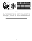
Replacement parts may be ordered from Sears Parts and Service
Centers or by calling 1-800-4-MY-HOME (1-800-469-4663).
When ordering replacement parts, always have the following
information ready:
1. model, serial, and product number
2. type of gas
3. item number
4. parts description
See the Parts Order List section for a list of available repair parts.
External Inspection & Cleaning of the
Base-Ring Filter
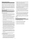
1. At least annually, check the base-ring filter (Figure 38) for
any dust or debris that may have accumulated on the filter
screen. NOTE: If the water heater is located in an area that
is subjected to lint and dirt, it may be necessary to check
the base-ring filter more frequently.
2. Follow the Lighting Instructions to turn off the water heater
and allow it to cool for 10 minutes before attempting to clean
the base-ring filter.
3. Use a vacuum cleaner with a hose attachment to remove
any dust or debris that may have accumulated on the filter.
NOTE: If unable to inspect or clean the base-ring filter, follow
the “Cleaning the Combustion Chamber and Flame-arrestor”
instructions.
4. After the base-ring filter has been cleaned, follow the
Lighting Instructions to return the water heater to service.
Removing the Manifold/Burner Assembly
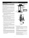
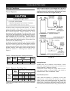
1. Turn off the gas supply to the water heater at the manual
gas shut-off valve. This valve is typically located beside the
water heater (Figure 11). Note the position of the shut-off
valve in the open/on position then proceed to turn it off.
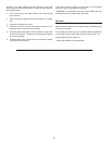
2. On the lower front of the water heater, locate the gas control
valve/thermostat (see Figure 32). Before performing any
maintenance, it is important to turn the temperature dial on
the gas control valve/thermostat to its lowest setting.
3. On top of the gas control valve/thermostat, turn the gas
control knob to the “OFF” position.
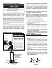
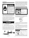
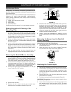
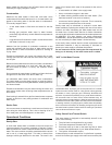
THERMOCOUPLE
MANIFOLD TUBE
PILOT
TUBE
WHITE RODGERS GAS VALVE
FIGURE 31.
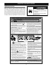
4. Remove the outer door.
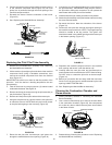
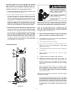
5. Remove the two screws securing the manifold door
assembly to the combustion chamber (Figure 32).
MANIFOLD
SCREWS (2)
MANIFOLD
COMPONENT BLOCK
MANIFOLD
DOOR
THERMAL
SWITCH
PILOT
TUBE
PIEZO
IGNITER
BUTTON
GAS CONTROL VALVE/
THERMOSTAT
MANIFOLD
TUBE
THERMOCOUPLE
VIEW PORT
FIGURE 32.
6. Disconnect the thermocouple (right-hand thread), pilot tube,
the igniter wire from the igniter button, the two connectors
attached to the thermal switch, and manifold tube at the gas
control valve/thermostat. (Figures 31 & 32.) NOTE: L.P. Gas
systems use reverse (left-hand) threads on the manifold tube.
7. Grasp the manifold tube and push down slightly to free the
manifold, pilot tube, and thermocouple.
8. Carefully remove the manifold/burner assembly from the
burner compartment. NOTE: Be sure not to damage internal
parts.
Removing the Burner from the Manifold/
Burner Assembly
Natural Gas (Low Nox) & L.P. Gas Burner
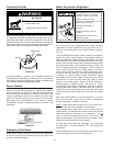
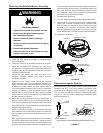
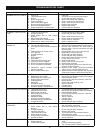
1. Take off the burner by removing the two (2) screws located
underneath the burner.
2. Check the burner to see if it is dirty or clogged. The burner
may be cleaned with soap and hot water (Figure 33).
BURNER
(BOTTOM VIEW)
SCREWS
PILOT ASSEMBLY
(BOTTOM VIEW)
FIGURE 33.
Replacing the Thermocouple
1. Remove the manifold/burner assembly as directed previously.
2. Lift the retainer clip straight up from the back of the manifold
component block (using a flat-blade screwdriver), then
remove the manifold component block from the manifold
door (Figure 34.)
3. Remove the burner. See “Removing the Burner from the
Manifold/Burner Assembly.”
4. Pull the thermocouple from the pilot assembly (Figure 35).
IMPORTANT: Be careful not to bend or alter the position of the
pilot assembly components.
5. Insert the thermocouple tip into the holes provided in the
pilot bracket until it clicks into place. NOTE: The base
of the thermocouple must be flush with the base of the
pilot bracket.