


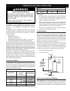

15
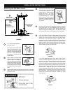
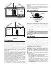
BACK
SIDES
TOP
VIEW
SIDES
VENT
FRONT
24” MINIMUM
FOR SERVICE
TOP
TO
CEILING
FIGURE 10.
Filling the Water Heater
Never use this water heater unless it is completely full of water.
To prevent damage to the tank, the tank must be fi lled with water.
Water must fl ow from the hot water faucet before turning “ON” gas
to the water heater. To fi ll the water heater with water:
• Close the water heater drain valve by turning the handle to
the right (clockwise). The drain valve is on the lower front of
the water heater.
Explosion Hazard
• Use a new CSA approved gas supply line.
• Install a shut-off valve.
• Do not connect a natural gas water heater to an
L.P. gas supply.
• Do not connect an L.P. gas water heater to a
natural gas supply.
• Failure to follow these instructions can result in
death, explosion, or carbon monoxide poisoning.
WARNING
Gas Requirements
IMPORTANT: Read the rating plate to be sure the water heater
is made for the type of gas you will be using in your home. This
information will be found on the rating plate located near the
gas control valve/thermostat. If the information does not agree
with the type of gas available, do not install or light. Call your
dealer.
NOTE: An odorant is added by the gas supplier to the gas used
by this water heater. This odorant may fade over an extended
period of time. Do not depend upon this odorant as an indication
of leaking gas.
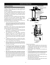
Gas Piping
The gas piping must be installed according to all local and state
GAS SUPPLY
codes or, in the absence of local and state codes, the “National
Fuel Gas Code”, ANSI Z223.1(NFPA 54)-current edition.
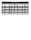
Tables 1 and 2 on the following page provide a sizing reference
for commonly used gas pipe materials. Consult the “National
Fuel Gas Code” for the recommended gas pipe size of other
materials.
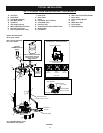
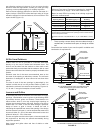
NOTE: Use pipe joint compound or teflon tape marked as being
resistant to the action of petroleum [Propane (L.P.)] gases.
(See Figure 11.)
1. Install a readily accessible manual shut-off valve in the gas
supply line as recommended by the local utility. Know the
location of this valve and how to turn off the gas to this unit.
2. Install a drip leg (if not already incorporated as part of
the water heater) as shown. The drip leg must be no less
than three inches long for the accumulation of dirt, foreign
material, and water droplets.
3. Install a ground joint union between the gas control valve/
thermostat and the manual shut-off valve. This is to allow
easy removal of the gas control valve/ thermostat.
4. Turn the gas supply on and check for leaks. Test all
connections by brushing on an approved noncorrosive
leak-detection solution. Bubbles will show a leak. Correct
any leak found.
CHECK WITH
LOCAL UTILITY
FOR MINIMUM HEIGHT
3” MINIMUM
DRIP LEG
GROUND
JOINT
UNION
SUITABLE DRAIN
MANUAL GAS
SHUT-OFF VALVE
6” MAXIMUM
AIR GAP
FIGURE 11.
• Open the cold water supply valve to the water heater.
NOTE: The cold water supply valve must be left open
when the water heater is in use.
• To ensure complete fi lling of the tank, allow air to exit by
opening the nearest hot water faucet. Allow water to run until
a constant fl ow is obtained. This will let air out of the water
heater and the piping.
• Check all water piping and connections for leaks. Repair as
needed.