


4. Remove the screw that secures the pilot shield and pilot
assembly to the pilot bracket (Figure 35). Keep the screw
for future use.
5. Loosen the nut securing the pilot tube to the pilot assembly.
NOTE: To prevent any bending of the pilot bracket, use
pliers to hold the pilot assembly bracket while loosening
the pilot nut.
6. Pull the pilot tube from the pilot assembly (Figure 35).
IMPORTANT: Be careful not to bend or alter the position of
the pilot assembly components.
7. Using the old pilot/pilot tube assembly as a guide, bend
the new pilot tube to match the old one. NOTE: Make only
the bends closest to the pilot before going to the next step.
DO NOT crimp or crease the pilot tube.
8. Push the new pilot assembly connectors through the hole
in the manifold door where the two piece wire connector
wilt be seated (See Figure 35). Reconnect the pilot tube
and tighten the nut securing it to the pilot assembly.
IMPORTANT: Keep the pilot orifice in the pilot when making
the connection. Do not operate the water heater without
the pilot orifice installed.
9. Reattach the pilotshield and pilot assembly to the pilot bracket.
10. Reattach the burner and secure with the screws
removed earlier. NOTE: See Figure 34 for correct burner
orientation.
11. Position the new pilot tube through the largest opening of
the two piece wire connector. NOTE: The largest opening
should be located at the top position. The igniter wire
should be located in the middle opening and thermopile
wires in the bottom opening.
12. Reposition the two piece wire connector in the manifold
door opening and secure it with the retainer clip.
13. Before you proceed to the next step, install the new brass
ferrule nut in the gas control valve/thermostat's pilot tube
opening. HAND TIGHTEN ONLY.
14. See "Replacing the Manifold/Burner Assembly."
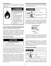
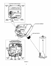
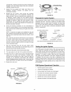
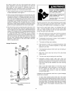
Thermopile
Connector
Wire
Pilot Tube _ _
Two Piece / _
Wire Connector
Burner and other fittings
not shown for clarity.
_tainer Clip
FIGURE 35.
Pilot
Thermopile
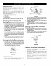
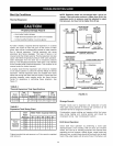
Cleaning the Combustion Chamber and
Flame-arrestor
1.
2.
Follow procedure outlined in "Removing the Manifold/
Burner Assembly."
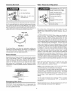
Use a vacuum cleaner/shop vac to remove all loose debris
in the combustion chamber (Figure 37). Use compressed
air to clear any dust or debris that may have accumulated
in the flame-arrestor.
COMBUSTION CHAMBER
FLAME ARRESTOR
DOOR GASKET
BASE-RING
FIGURE 37.
3. Reassemble by following the procedure under "Replacing
the Manifold/Burner Assembly."
Replacing the Manifold/Burner Assembly
Explosion Hazard
Tighten both manifold door screws securely.
Remove any fiberglass between gasket
and combustion chamber.
Replace viewport if glass is missing or
damaged.
Replace two piece wire connector if missing or
removed.
• Replace door gasket if damaged.
• Failure to follow these instructions can result
in death, explosion, or fire.
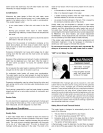
Thermopile
Connector
Thermal
Connectors
1. Check the door gasket for damage or imbedded debris
prior to installation.
2. Inspect the view port for damage and replace as required.
3. Insert the manifold/burner assembly into the burner
FIGURE 36.
31