


A. Tools required:
1. T15 Torx Screwdriver
2. 3/16" slotted screwdriver.
3. Open-end wrenches 7/16", and 3/4".
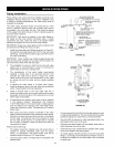
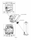
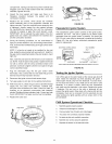
For these instructions, please see Figure 31.
B. Removing the Electronic Control Module:
1. Turn the gas control/temperature knob to the "OFF"
position.
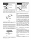
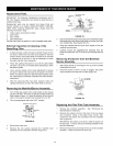
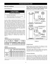
2. Turn off the gas at the manual shut-off valve on the gas
supply line (Figure 11).
3. Disconnect the wire connectors from the piezo igniter, tank
sensors, and thermopile mounted on the lower front of the
gas control valve assembly.
4. Remove the torx screw located beside the pilot tube on the
lower front of the electronic control module with a T15 torx
screwdriver.
5. Depress the two plastic locking tabs on the top surface
of the electronic control module with a 3/16" slotted
screwdriver.
6. Grasp the sides of the electronic control module and pull
outward to remove.
C. Removing the Gas Valve Assembly:
IMPORTANT: This water heater has a resettable thermal switch
installed. Do not attempt to disable or modify this feature in any
way. Use only factory authorized replacement parts.
1. Follow steps 1 to 6 in B above to remove the electronic
control module.
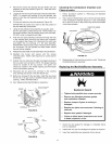
2. Refer to the "Gas Piping" section (Figure 11)and disconnect
the ground joint union in the gas piping. Next, disconnect
the inlet gas supply to the gas valve.
3. Loosen the flare nut that connects the pilot tube to the
bottom of the gas control valve assembly with a 7/16" open-
end wrench. Pull down on the pilot tube to separate the tube
from the gas valve.
4. Loosen the flange nut that connects the burner tube to
bottom of gas control valve with a 314" open-end wrench.
Pull down on the burner tube to separate the tube from the
gas valve.
5. Unscrew and remove the gas valve assembly and backplate
by turning it to the left. Continue until it separates from the
gas valve nipple that is threaded into the tank. (The gas
valve nipple remains attached to the tank.)
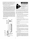
6. Check for water leaks around the threads of the gas valve
nipple (which is still attached the tank). If leaks appear,
drain the tank and contact a qualified service technician.
(Refer to the "Draining and Flushing" section.)
D: Installing a Gas Control Valve/Thermostat
(Full Assembly)
NOTE: If the electronic control module, gas valve, and backptate
are not assembled, assemble them before proceeding.
1. If it is not needed, remove the metal gas valve nipple from
the gas control valve/thermostat. (It is screwed onto the
threaded plastic nipple of the gas control valve/thermostat's
backplate.)
IMPORTANT: You can use the metal gas valve nipple that
is already installed in the tank. However, if you need to
install a new gas valve nipple, drain the water heater before
removing the old one from the tank.
2. Screw the new gas control valve into the tank opening, then
hand tighten it. DO NOT OVER TIGHTEN or damage may
result. Check for water leaks when you are finished.
3. Reconnect the manifold tube, pilot tube, and inlet gas supply
line to the gas valve. Tighten securely. NOTE: Use an
approved Teflon ®tape or pipe compound on the gas piping
connections.
4. Connect the thermopile, tank sensor, and igniter wire
plugs.
5. Turn on the gas supply and test the gas supply connections
by brushing on an approved noncorrosive leak detection
solution. Bubbles forming indicate a leak. Correct any leak
found.
6. Check the operation of the burner by following the lighting
instructions on the front of the water heater. With the burner
lit, check the gas control valve/thermostat supply line,
manifold tube and pilot tube connections for leaks.
E: Installing the Electronic Control Module:
1. Align the two plastic locking tabs on the top surface of the
electronic control module with the openings of the gas valve
back-plate. Press on the front of the control module until it
locks into position.
2. Reinstall the torx screw on the lower front of the electronic
control module (beside pilot tube) with a T15 torx screwdriver.
Tighten securely.
3. Reconnect the wire connectors from the piezo igniter, tank
sensors, and thermopile to the electronic control module.
4. Light the heater following the lighting and operating
instructions on the front surface of the heater.
TEFLON®is a registered trademark of E.I. Du Pont De Nemours
and Company.
28