


10
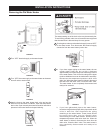
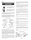
Optional Installation Instructions
Some compact models have optional plumbing
connections. On these units, if top connection is
preferred over the side connection, use the following
instructions as they apply to your connection:
To change Temperature and Pressure (T&P) valve
location: Remove 3/4” plug from opening in jacket
top. Replace 3/4” plug opening with T&P valve;
plug original T&P valve opening with 3/4” plug. BE
SURE TO REAPPLY PIPE JOINT COMPOUND OR
TEFLON TAPE AROUND THE THREADED ENDS
OF THE TEMPERATURE AND PRESSURE (T&P)
VALVE AND THE 3/4” PLUG WHEN REINSTALLING
COMPONENTS.
To change Cold Inlet location: Remove 3/4” plug from
opening in jacket top. Replace 3/4” plug opening with
Cold Inlet nipple; plug original Cold Inlet opening with 3/4”
plug. BE SURE TO REAPPLY PIPE JOINT COMPOUND
OR TEFLON TAPE AROUND THE THREADED ENDS
OF THE COLD INLET NIPPLE AND THE 3/4” PLUG
WHEN REINSTALLING COMPONENTS.
To change Hot Outlet location: Screw 3/4” NPT galvanized
cap (not included, purchase locally) onto Side Hot Outlet
and install 3/4” NPT nipple (not included, purchase
locally) in the opening identified as HOT/T&P location.
BE SURE TO REAPPLY PIPE JOINT COMPOUND
OR TEFLON TAPE AROUND THE THREADED ENDS
OF THE 3/4” NPT NIPPLES WHEN REINSTALLING
COMPONENTS.
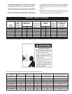
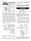
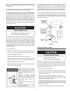
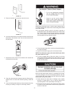
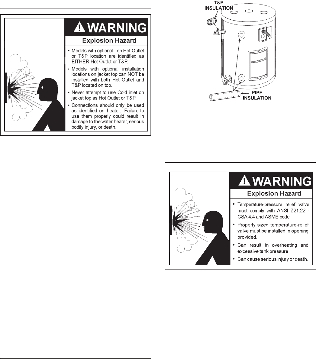
T & P Valve and Pipe Insulation
Remove insulation for T & P valve and pipe connections from
carton.
Fit pipe insulation over the incoming cold water line and the
hot water line. Make sure that the insulation is against the side
jacket of the heater.
Fit T & P valve insulation over valve. Make sure that the insulation
does not interfere with the lever of the T & P valve.
Secure all insulation using tape.
FIGURE 9A.
NOTE: Figure above is used to illustrate installation of
T&P and pipe insulation only. As indicated in PRODUCT
SPECIFICATION Section. Actual optional Cold & Hot / T&P
spud location vary from model to model.
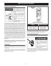
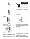
Temperature-Pressure Relief Valve
This heater is provided with a properly certied combination
temperature - pressure relief valve by the manufacturer.
The valve is certied by a nationally recognized testing laboratory
that maintains periodic inspection of production of listed equipment
of materials as meeting the requirements for Relief for Hot
Water Supply Systems, ANSI Z21.22 • CSA 4.4, and the code
requirements of ASME.
If replaced, the valve must meet the requirements of local codes,
but not less than a combination temperature and pressure relief
valve certied as indicated in the above paragraph.
The valve must be marked with a maximum set pressure not to
exceed the marked hydrostatic working pressure of the water
heater (150 psi = 1,035 kPa) and a discharge capacity not less
than the water heater input rate as shown on the model rating
plate. (Electric heaters - watts x 3.412 equal Btu/hr input rate)
Your local jurisdictional authority, while mandating the use
of a temperature-pressure relief valve complying with
ANSI Z21.22 • CSA 4.4, may require a valve model different
from the one furnished with the water heater.
Compliance with such local requirements must be satised
by the installer or end user of the water heater with a locally