


In Canada
The Canada the standard has been established by the
Canadian Standard Association. The installation must
conform to CAN/CSA-B365, Installation Code for
Solid Fuel Burning Appliances and Equipment.
Before proceeding be sure to consult your local
building inspector.
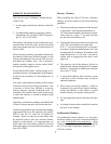
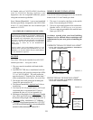
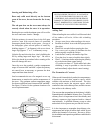
Common Method
This method requires the removal of all combustible
materials from at least 18 (457mm) around the
chimney connectors proposed location. With a 6
round liner the minimum area required would be
43 x 43 square.
It is important to remember to locate the pass-through
at least 18 from the ceiling to maintain the proper
clearance to combustibles.
The space that is cleared of combustible materials
must then remain empty. Sheet metal panels can then
be used to cover the area. However, when using a
panel on both sides of the wall each cover must be
installed on noncombustible spacers at least 1 from
the wall. If one panel of sheet metal is to be used it
may be installed flush to the wall.
SEE SECTION 5.3.1 and 5.3.2 of CAN/CSA -
B365-M91.
Consult your local building inspector, authorized Jøtul
Dealer, NFPA 211 in the U.S. or CAN/CSA-B635
in Canada for other approved wall pass-through
methods.
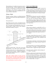
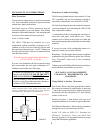
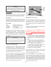
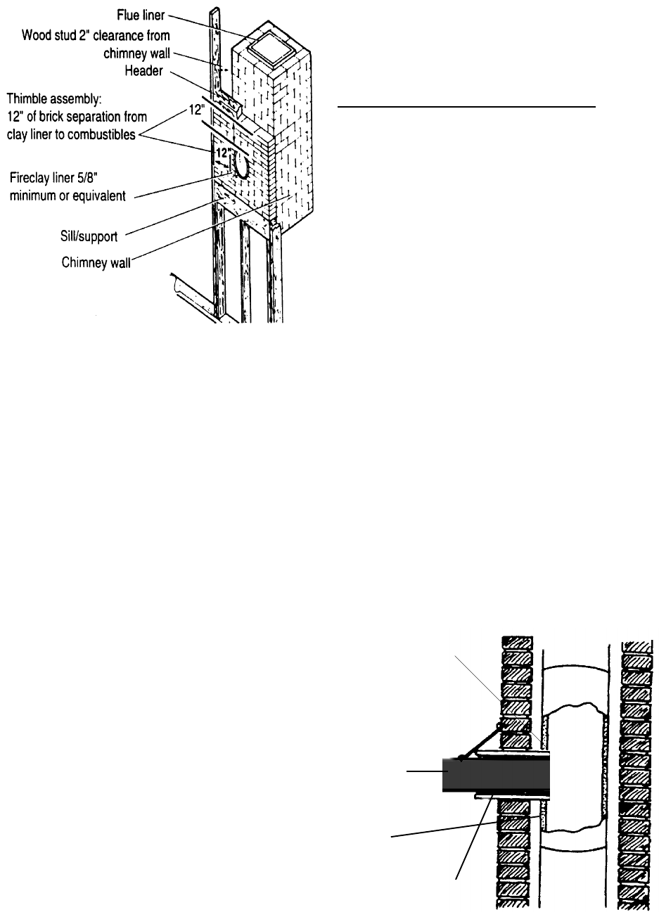
CONNECTING TO THE CHIMNEY
Masonry Chimney
When installing a OSLO F500 into a masonry
chimney through a thimble(the opening through the
chimney wall to the flue), the thimble must be lined
with ceramic tile or metal and be securely cemented
in place.
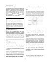
The chimney connector/stove pipe must slide
completely inside the thimble to the inner surface or
the flue liner. It may be necessary to make use of a
thimble sleeve (a pipe with a slightly smaller diameter
than standard stove pipe). This special pipe can be
easily installed into a thimble.
See figure 4.
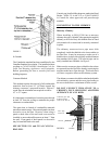
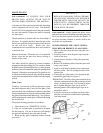
Make sure the connector pipe or thimble sleeve does
not protrude into the flue liner, thereby restricting the
area the smoke has to flow through. This bottle-neck
will have a negative affect on the chimney system.
The chimney connector should be sealed at the thimble
with refractory cement and the stove pipe leading to
the stove should have a minimum of three screws.
DO NOT CONNECT THIS STOVE TO A
CHIMNEY FLUE SERVICING ANOTHER
APPLIANCE OF ANY KIND.
Connector pipe shall
be flush with the
inside of the flue tile
7
Thimble
Stove pipe
connector
Flue tile
FIGURE 3
FIGURE 4