INSTALLATION
IF THIS SOLID FUEL ROOM HEATER IS NOT
PROPERLY INSTALLED A HOUSE FIRE MAY
RESULT. FOR YOUR SAFETY, FOLLOW THE
INSTALLATION DIRECTIONS. CONTACT
THE LOCAL BUILDING OR FIRE OFFICIALS
ABOUT RESTRICTIONS AND
INSTALLATION INSPECTION
REQUIREMENTS IN YOUR AREA.
TOP OR REAR EXIT FLUE
The Oslo F500 is shipped with the flue collar,
gasketing and hardware inside the stove. To install
the flue collar in the top or rear exit position remove
the tape from the gasketing and adhere to the groove
on the back of the stove around the flue opening.
Place the flue collar on the stove in the top or rear
exit position and secure with the nut, bolt and washer.
The nut and washer are placed on the inside of the
stove.
STOVE PIPE
CHIMNEY CONNECTOR
The chimney connector is a single walled pipe used
to connect the stove to the chimney. For use with
the OSLO F500 the chimney connector MUST be
6 in diameter, with a minimum thickness of 24 gauge
black steel.
Aluminum and Galvanized steel pipe is not acceptable
for use with the OSLO F500. These materials
cannot withstand the extreme temperatures of a
wood fire and can give off toxic fumes when heated.
Do not use the connector pipe as a chimney.
For the best performance the chimney connector
should be as short and direct as possible, with no
more than two 90° elbows. The maximum horizontal
run is 36 and a recommended total length of stove
pipe should not exceed 10 feet. Always slope
horizontal runs upward ¼ per foot toward the
chimney.
No part of the chimney connector may pass through
an attic or roof space, closet or other concealed
space, or through a floor or ceiling. All sections of
the chimney connectors must be accessible for
cleaning. Where passage through a wall or partition
of combustible construction is desired, the installation
must conform with NFPA 211 or CAN/CSA-B365,
and is also addressed in this manual.
DO NOT CONNECT THIS UNIT TO A
CHIMNEY FLUE SERVICING ANOTHER
APPLIANCE.
Reminder:
Your local officials have final authority in
determining if a proposed installation is
acceptable. Any requirement, that is requested
by the local authority having jurisdiction, that is
not specifically addressed in THIS manual,
defaults to NFPA 211, and local codes in the
U.S. or in Canada, CAN/CSA-B365-M and local
codes.
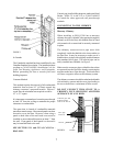
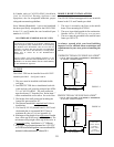
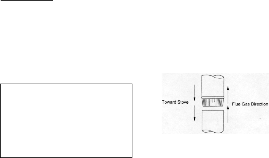
Each chimney connector or stove pipe section must
be installed to the stove flue collar and to each other
with the male (crimped) end toward the stove.
See
figure 1.
This prevents any amount of condensed or liquid
creosote from running down the outside of the pipe
or the stove top. All joints, including the flue collar
connection must be secured with three sheet metal
screws to ensure that the sections do not separate.
4
FIGURE 1
DO NOT CONNECT THIS STOVE TO ANY
AIR DISTRIBUTION DUCT OR SYSTEM.


