


341426-BIM-A-0108
6 Johnson Controls Unitary Products
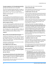
THERMOSTAT
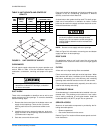
The room thermostat should be located on an inside wall
approximately 56" above the floor where it will not be subject
to drafts, sun exposure or heat from electrical fixtures or
appliances. Follow manufacturer's instructions enclosed with
the thermostat for general installation procedure. Four color
coded insulated wires (minimum #18 AWG) should be used
to connect thermostat to unit. See Figure 3.
POWER AND CONTROL WIRING
Field wiring to the unit must conform to provisions of the cur-
rent N.E.C. ANSI/NFPA No. 70 or C.E.C. and/or local ordi-
nances. The unit must be electrically grounded in accordance
with local codes or, in their absence, with the N.E.C./C.E.C.
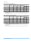
Voltage tolerances which must be maintained at the com-
pressor terminals during starting and running conditions are
indicated on the unit Rating Plate and Table 8.
The wiring entering the cabinet must be provided with
mechanical strain relief.
A fused disconnect switch should be field provided for the
unit. If any of the wire supplied with the unit must be replaced,
replacement wire must be of the type shown on the wiring
diagram.
Electrical line must be sized properly to carry the load. Each
unit must be wired with a separate branch circuit fed directly
from the meter panel and properly fused.
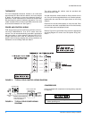
Refer to Figure 4 for typical field wiring and to the appropriate
unit wiring diagram for control circuit and power wiring infor-
mation.
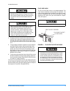
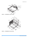
COMPRESSORS
Units are shipped with compressor mounting factory-adjusted
for shipping.
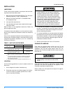
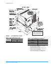
FIGURE 3 - TYPICAL FIELD CONTROL WIRING DIAGRAM
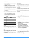
FIGURE 4 - TYPICAL FIELD POWER WIRING
DIAGRAM
CONTACTOR
GROUND
LUG
FIELD-SUPPLIED
DISCONNECT
REFER TO ELECTRICAL
DATA TABLES TO SIZE
THE DISCONNECT
THREE
PHASE
POWER
SUPPLY
Loosen compressor mounting bolts a half turn
before operating unit.