


341426-BIM-A-0108
Johnson Controls Unitary Products 23
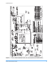
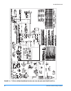
TYPICAL WIRING DIAGRAM NOTES
(SEE FIGURES 14 AND 15)
1. All field wiring to be accomplished following city, local
and/or national codes in effect at time of installation of
this unit.
2. Caution: Label all wires prior to disconnection when ser-
vicing controls. Wiring errors can cause improper and
dangerous operation. If any of the wire as supplied with
this unit must be removed it must be replaced with type
105°C, 600V wire or equivalent clearly renumbered for
identification. Verify proper operation after servicing.
3. Motors inherently protected.
4. Factory wired for 460V operation.
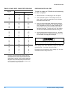
5. See unit nameplate for maximum fuse size and/or circuit
breaker size and minimum circuit ampacity.
6. If both LR and ASCT are present, wire 801/BL and 805/
BL are connected to ASCT-3. If only LR is present wire
801/BL and 805/BL are connected to M1 coil. If only
ASCT is present wire 202/Y is connected to ASCT-3. If
neither LR or ASCT are present, wire 202/Y is connected
to M1 coil as shown.
7. Shunt contact also used with crankcase heater.
(optional)
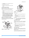
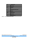
8. Unit factory wired for low or medium speed indoor blower
operation. To change motor speed, connect speed tap
wires from indoor blower motor, per Detail A (Figure 16).
Tape unused speed tap wires to prevent shorting and
secure.
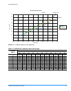
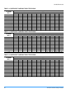
9. Select indoor blower speed to remain within the temper-
ature rise range on the nameplate in heating.
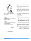
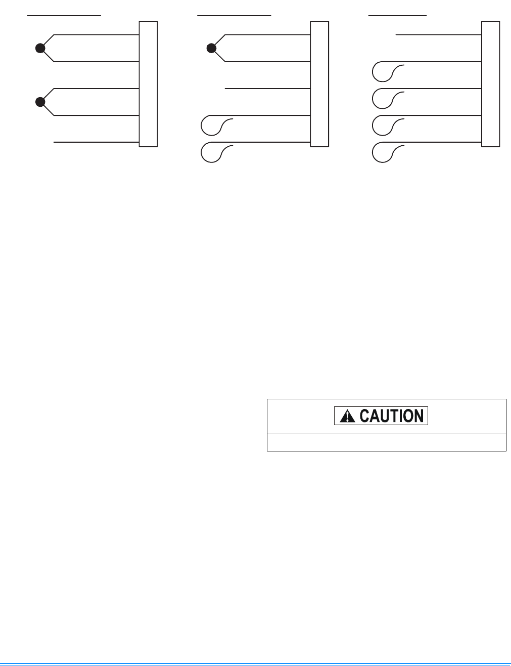
FIGURE 16: WIRING DIAGRAM DETAIL A (460-3-60 POWER SUPPLY)
1
1.
See Figure 15.
LOW SPEED
MED SPEED
HI SPEED
(BR-LI)
(BR-LI)
(BR-LI)
ID FAN MOTOR
ID FAN MOTOR
ID FAN MOTOR
BLK (HI)
BLK / WHT BLK / WHT BLK / WHT
BLU (MED) BLU (MED) BLU (MED)
BLU / WHT BLU / WHT BLU / WHT
RED (LOW) RED (LOW) RED (LOW)
BLK (HI) BLK (HI)
Open all disconnects before servicing this unit.