


341426-BIM-A-0108
Johnson Controls Unitary Products 15
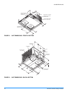
2. Pressure Switch (PS) - If the draft motor should fail, the
pressure switch prevents the ignition controls and gas
valves from being energized.
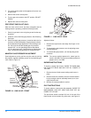
3. Flame Sensor - The flame sensor and controls are
located per Proper Flame Adjustment, Figure 12. If an
ignition control fails to detect a signal from the flame sen-
sor indicating the pilot flame is properly ignited, then the
main gas valve will not open.
4. Rollout Switch (RS) - This switch is located in the
burner vestibule. In the event of a sustained main burner
flame rollout, it shuts off the ignition control and closes
the main gas valve.
NOTE: The manual reset Rollout Switch (RS) must be reset
before allowing furnace operation.
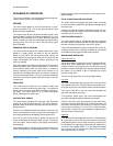
5. Auxiliary Limit Switch (ALS) - This control is located
inside the heat exchanger compartment and is set to
open at 160°F. It is a manual reset switch. If ALS trips,
then the primary limit (LS) has not functioned correctly.
Replace the primary limit LS.
COOLING
When the thermostat calls for COOL, the thermostat termi-
nals G and Y are energized signaling the compressor and
outdoor fan to run.
With a call for Y, the circulating fan is energized at cooling
speed.
When the thermostat is satisfied, terminals G and Y are de-
energized, de-energizing the compressor and outdoor fan.
After a cool fan off delay timing of 30 seconds the circulating
fan is de-energized.
CIRCULATING FAN
When the thermostat calls for FAN, the thermostat terminal G
is energized signaling the circulating fan to run at the cool
speed.
If a call for COOL occurs, the circulating fan continues to run
at the cool speed.
If a call for HEAT occurs, the circulating fan switches to heat
speed after a 30 second delay.
When the thermostat ends the call for FAN, the thermostat
terminal G is de-energized, de-energizing the circulating fan.
START-UP
PRE-START CHECK LIST
Complete the following checks before starting the unit.
1. Check the type of gas being supplied. Be sure that it is
the same as listed on the unit nameplate.
2. Make sure that the vent outlet air hoods has been prop-
erly installed.
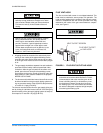
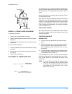
OPERATING INSTRUCTIONS
1. STOP! Read the information on the unit safety label.
2. Set the thermostat to the OFF position.
3. Turn off all electrical power to the unit.
4. DO NOT try to light the burners by hand. This appliance
is equipped with an ignition device which automatically
lights the burners.
5. Remove the access panel.
6. Turn the gas valve switch to the OFF position.
7. Wait five (5) minutes to clear out any gas. If you then
smell gas, STOP! Follow B in the information on the unit
safety label. If you don't smell gas, go to the next step.
8. Turn the gas valve switch to the ON position.
9. Replace the control access panel.
10. Turn on all electric power to the unit.
11. Set the thermostat to the desired setting.
12. If the unit will not operate, follow the instructions To Turn
Off Gas To Appliance and call your service technician or
gas supplier.
TO TURN OFF GAS TO UNIT
1. Set the thermostat to the OFF position.
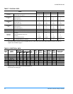
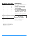
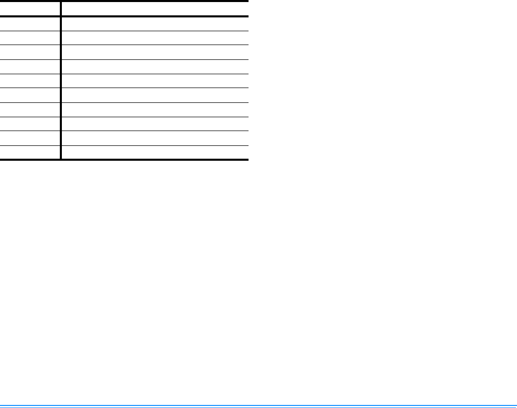
TABLE 11: IGNITION CONTROL BOARD FLASH
CODES
Flash Code Description
Heart Beat Normal Operation
2 Flashes Pressure switch open with inducer on
3 Flashes Pressure switch closed with inducer off
4 Flashes Not Used
5 Flashes Lockout from too many flame losses
6 Flashes High temperature switch open
7 Flashes Rollout switch open
8 Flashes Flame present with gas off
9 Flashes Gas valve stuck OFF or ON
10 Flashes Flame sense circuit failure