


6544X-X (en) Page 7 of 8
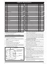
Air leakage out of main exhaust.
Worn (14) insert. Replace (14) insert.
Worn (12) valve plate and pin assembly. Replace (12)
valve plate and pin assembly.
Damaged (24) piston assembly. Replace (24) piston as-
sembly.
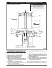
REASSEMBLY OF AIR MOTOR (CONT’D)
26. Fit the turned diameter of the 90350 special installation
tool into the bore in the bottom of (19) head assembly.
27. Place (38) adapter assembly down over (36) extension
rod, with the thread on the (38) adapter up.
28. Insert (32) washer into the groove on the top of (36) ex-
tension rod.
29. Pull (38) adapter up around the (32) washer.
30. Place (17) washer over (36) extension rod and onto (38)
adapter.
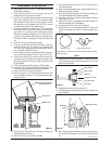
31. Clean with solvent and put Loctite 271 on the threads of
(38) adapter. Screw (31) valve piston onto (38) adapter
and tighten (see gure 4, page 3).
32. Push the assembled (38) adapter and (31) valve piston
down thru the 90350 special installation tool until it bot-
toms.
33. Remove the 90350 special installation tool by pulling up
on it.
34. Install (33) gland assembly over the (31) valve piston and
push down, being careful to retain (34) seal in the “O”
ring groove.
35. Align the two screw holes and secure (33) gland assem-
bly to (19) head assembly with two (6) screws and two (7)
lock washers.
36. Insert (13) insert spring assembly into the (19) head
assembly, with the hooks down and the nylon roller to-
ward (31) valve piston.
37. Apply grease to both (11 and 14) inserts and place them
in position (see gure 10) with legs of insert toward (31)
valve piston and the larger, (14) insert, located in front of
the larger diameter nylon roller. Also, the nylon roller on
the (13) insert spring assembly should be between the
legs of both (11 and 14) inserts.
38. Apply grease to gasket side of (12) valve plate and put
(15) gasket on (12) valve plate. To determine the correct
side, the screw holes nearest the top and bottom of (12)
valve plate are toward the exhaust port on the (19) head
assembly. Also, the (12a) roll pins in (12) valve plate are
at the top.
39. Hold the (11 and 14) inserts against the (31) valve piston
and slide the (15) gasket and (12) valve plate between
the two inserts and (19) head assembly. Be sure the
larger holes in the (12) valve plate are located in front of
the larger or (14) insert. Also, be sure the pins are located
at the top of the valve plate.
40. Hook the round coil in (13) insert spring assembly over
the (12a) roll pins (see gure 10).
41. Hook the bottoms of the (13) insert spring assembly into
the holes on the side of (12) valve plate (see gure 10).
42. Insert (9) valve guide against the face of (12) valve plate.
The legs of (9) valve guide should be down, with the leg
having the threaded hole nearest the bottom located
nearest the exhaust port of the (19) head assembly.
43. Place (5) washer on each of the four (4) screws and insert
into the provided holes and tighten evenly across the
corners. NOTE: To ease the alignment of the holes, an “O”
ring pick is helpful.
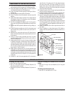
44. Install (10) gasket in (8) air motor cap and secure with six
(3) screws.
45. Place (2) de ector on the exhaust port of (19) head as-
sembly, with the opening down, and secure with four (1)
screws.
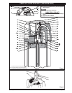
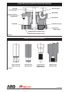
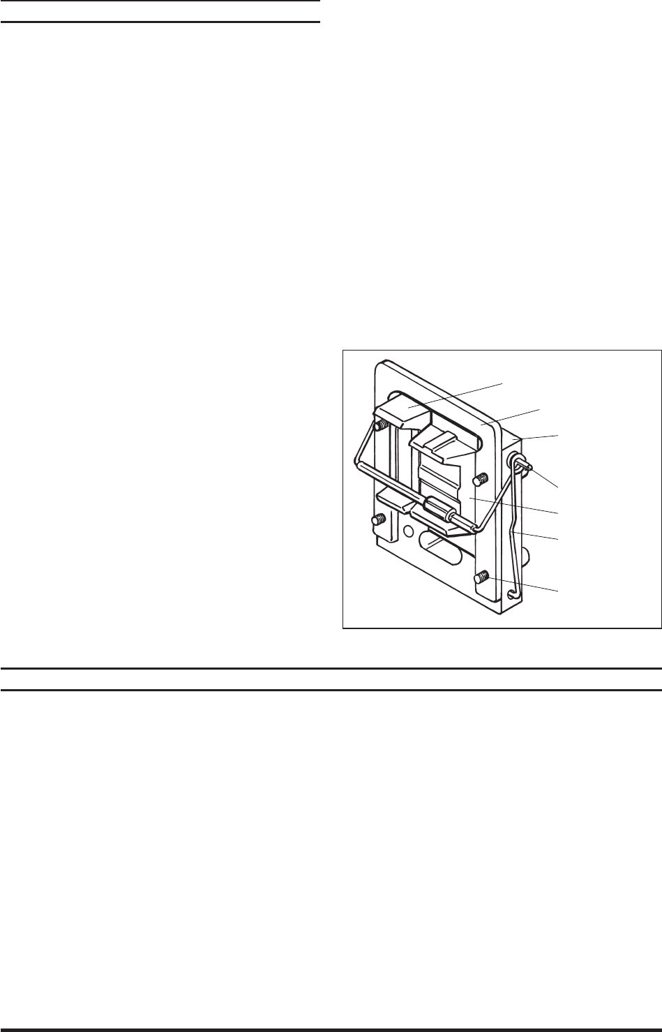
12 - Valve Plate and
Pin Assembly
12a - Roll Pin
14 - Valve Insert
13 - Insert Spring
Assembly
4 - Screw (4)
5 - Washer (4)
11 - Insert
9 - Valve Guide
Figure 10
TROUBLE SHOOTING
Continual air leakage out of bleeder hole in (19) head as-
sembly.
Worn (35) “O” ring or (34) seal. Replace (35) “O” ring and
(34) seal.
Air leakage around (48) piston rod.
Worn (45) “U” cup. Replace (45) “U” cup.