


6544X-X (en) Page 5 of 8
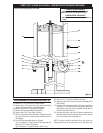
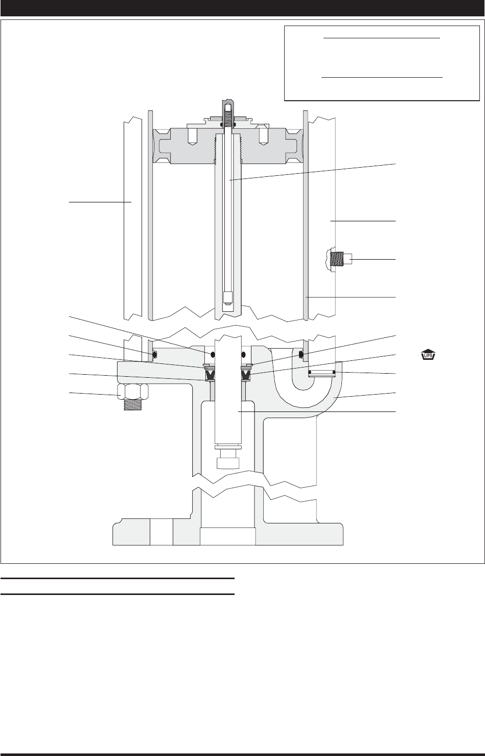
Remove (21) “O” ring from (19) head assembly.
Remove four (22) screws from (39) gland, permitting
gland to be removed from (19) head assembly.
Remove (16 and 41) “O” rings from (39) gland.
Remove (29) tube assembly from (30) base.
Remove two (18) “O” rings from (29) tube.
Remove (28) cylinder from (30) base. Usually during this
step, the (24) piston and (48) piston rod will remain in
(28) cylinder.
From (30) base assembly (there are 2 types):
Type 1 (see gure 5, above): Remove (43) snap ring, (44)
washer, (45) “U” cup and (46) washer.
Type 2 (see gure 11, page 8): Remove (49) “O” ring.
22.
23.
24.
25.
26.
27.
28.
Remove (21) “O” ring from (30) base assembly.
Separate (48) piston rod and (24) piston assembly from
(28) cylinder.
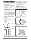
Unscrew (36) extension rod from (27) rod assembly by
holding (27) rod assembly with adjustable type pliers
and placing a wrench on the provided wrench flats at
the top of (36) extension rod.
Unscrew (48) piston rod from (24) piston assembly. Use
provided wrench ats on (48) piston rod. Next, remove
(27) rod assembly from (48) piston rod.
NOTE: Caution should be exercised so as not to mar or
damage the finish on (36) extension rod or (48) piston rod.
29.
30.
31.
32.
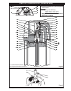
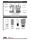
PARTS LIST / 6544X-X & 6546X-X - (AIR MOTOR PISTON ROD AND BASE)
DISASSEMBLY OF AIR MOTOR (CONT’D)
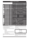
TORQUE REQUIREMENTS
NOTE: DO NOT OVERTIGHTEN FASTENERS.
Tighten (48) rod to 50 - 60 ft lbs. (67.8 - 81.3 Nm).
LUBRICATION / SEALANTS
NOTE: Lubricate with Parker “O” ring lube (ARO p/n
36460).
See chart on the opposite page for each model.
49
21
44
46
47
42
43
45
18
30
48
29
52
27
28
Figure 5