


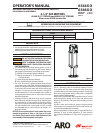

Page 2 of 8 6544X-X (en)
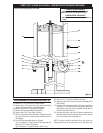
DISASSEMBLY OF AIR MOTOR
NOTE: All threads are right hand.
Place motor in up stroke position. This can be accom-
plished by pushing (48) rod toward the top of the air
motor.
Remove four (1) screws from (2) de ector.
Remove (2) de ector.
Remove six (3) screws from (8) air motor cap.
Remove (8) air motor cap and (10) gasket.
Loosen four (4) screws (which hold (12) valve plate and
(9) valve guide) until (9) valve guide can be removed by
pulling upward (see gure 9, page 6).
1.
2.
3.
4.
5.
6.
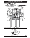
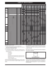
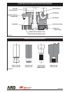
PARTS LIST / 6544X-X & 6546X-X
Item Description
(size)
(Qty) Part No.
1 Screw
(#8 - 32 x 7/8”) (not shown)
(4) Y136-90-S
2 De ector
(not shown)
(1) 90409
3 Screw
(#10 - 24 x 1/2”)
(6) 95956827
4 Screw
(#8 - 32 x 3/4”)
(4) Y19-89-S
5 Washer (4) 90084
6 Screw
(1/4” - 28 x 3/4”)
(2) Y119-49-C
7 Washer
(1/4” i.d.)
(2) Y14-416
8 Air Motor Cap (1) 90078
9 Valve Guide (1) 90093
10 Gasket (1) 90083-1
11 Insert (1) 90097
12 Valve Plate and Pin Assembly (1) 65028
12a Roll Pin
(3/32” o.d. x 3/4” long)
(2) Y178-26-S
13 Insert Spring Assembly (1) 65032
14 Valve Insert (1) 90796
15 Gasket (1) 90091
16 “O” Ring
(1/16” x 1-3/8” o.d.)
(2) Y325-26
17 Washer (1) 91344
18 “O” Ring
(1/16” x 3/4” o.d.)
(2) Y325-16
19 Head Assembly (1) 65889
20 “U” Cup
(3/16” x 1-3/8” o.d.)
(1) Y186-51
21 “O” Ring
(1/8” x 4-1/4” o.d.)
(2) Y325-242
22 Screw
(#8 - 32 x 3/8”)
(4) Y136-85-S
24 Piston Assembly (1) 61851
27 Rod Assembly
(see chart, page 4)
(1) - - - - -
Item Description
(size)
(Qty) Part No.
28 Cylinder
(see chart, page 4)
(1) - - - - -
29 Tube
(see chart, page 4)
(1) - - - - -
30 Base and Bearing Ass’y
(see chart, page 4)
(1) - - - - -
31 Valve Piston (1) 92394
32 Washer (1) 90105
33 Gland (1) 91006
34 Seal (1) 91007
35 “O” Ring
(0.103” x 1.255” o.d.)
(1) 91207
36 Extension Rod (1) 90080
38 Adapter (1) 92393
39 Gland (1) 90114
40 Washer (1) 91345
41 “O” Ring
(1/16” x 7/16” o.d.)
(1) Y325-11
42 Bolt
(see chart, page 4)
(4) - - - - -
43 Snap Ring
(see chart, page 4)
(1) - - - - -
44 Washer
(see chart, page 4)
(1) - - - - -
45 “U” Cup
(see chart, page 4)
(1) - - - - -
46 Washer
(see chart, page 4)
(1) - - - - -
47 Nut
(see chart, page 4)
(4) - - - - -
48 Piston Rod
(see chart, page 4)
(1) - - - - -
49 “O” Ring
(see chart, page 4)
(1) - - - - -
50 Ground Lug (1) 93006
51 Ground Label
(not shown)
(1) 93007
Items included in Service Kit 61268
(continued on page 5)
“Smart Parts”, keep these items on hand in addition to the service kits
for fast repair and reduction of downtime.
Includes item (12a) roll pin (qty 2).
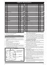
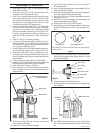
Figure 2
(Use an Allen wrench to
push out screws and
washers as shown.)
4 Screws (4)
5 Washers (4)
Allen Wrench
Remove four (4) screws and four (5) washers from (19)
head assembly by pressing outward with a small allen
wrench, as illustrated in gure 2.
With the aid of a screwdriver, unhook the legs of (13) in-
sert spring assembly from the bottom of (12) valve plate.
Remove (12) valve plate and (13) insert spring assembly
from (19) head by pulling upward. If (12) valve plate is
stuck, tap the top edge lightly with a soft face mallet. Do
not tap with anything metallic.
Remove both (11 and 14) inserts and (13) insert spring
assembly from (12) valve plate.
Remove (15) gasket from (19) head assembly.
Remove two (6) screws and two (7) lock washers from
(33) gland in (19) head assembly.
With fingers, pull (31) valve piston upward until (33)
gland has pulled out of its chamber.
Remove (33) gland by sliding it up over (31) valve piston.
Remove (34) seal and (35) “O” ring from (33) gland (see
gure 8, page 6).
Disassemble (31) valve piston from (38) adapter as
shown in gure 4, page 3.
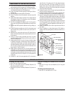
Pull (38) adapter upward until assembly is taut and
grasp (36) extension rod with ngers, as shown in gure
9, page 6. Grasp (36) extension rod below (38) adapter.
Now push (38) adapter down on (36) extension rod and
remove (32) washer from (36) extension rod. Now re-
move (38) adapter.
Remove (17) washer and (20) “U” cup from (38) adapter.
Remove four (47) nuts from four (42) bolts.
Remove four (42) bolts.
Remove (19) head assembly and place on the work-
bench with (8) cap side down. This action will allow (40)
washer to fall out of its cavity.
7.
8.
9.
10.
11.
12.
13.
14.
15.
16.
17.
18.
19.
20.
21.