


Page 6 of 8 6544X-X (en)
REASSEMBLY OF AIR MOTOR
Apply grease to all “O” rings, “U” cups and other rubber
goods before installing.
Clean the threads on (27) rod assembly and put the
threaded end thru (24) piston assembly.
Hold (27) rod assembly below threads with locking type
pliers. After applying Loctite 271 to the threads, attach
(36) extension rod and draw up tight, using the wrench
ats provided on (36) extension rod. NOTE: Do not mar
or damage the surface of (36) extension rod.
Place the “machined shoulder” end of (27) rod assembly
into the hole in the end of (48) piston rod. After apply-
ing Loctite 271 to threads, secure (48) piston rod into
(24) piston assembly and tighten to 50 - 60 ft lbs. (67.8 -
81.3 Nm), using provided wrench ats on (48) piston rod.
NOTE: Do not mar or damage the surface of (48) piston
rod.
Install (21) “O” ring on (30) base assembly.
On type one (30) base assembly (see figure 5, page 5),
install (46) washer, (45) “U” cup (lips up), (44) washer and
(43) snap ring. On type two (30) base assembly (see g-
ure 11, page 8), install (49) “O” ring.
Push (48) piston rod thru (30) base assembly, being care-
ful not to damage the lips of (45) “U” cup or (49) “O” ring.
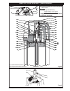
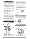
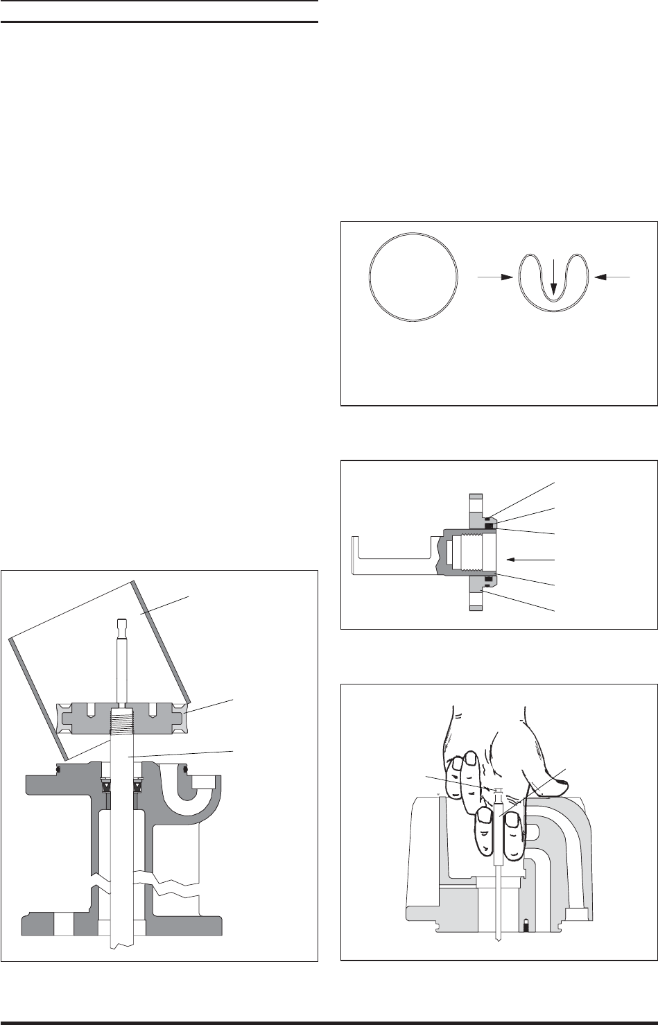
Grease the inside of (28) cylinder and fill the area be-
tween the lips of (24) piston assembly with grease, then
place (28) cylinder over (24) piston and rod assembly (see
gure 6 below).
Push (24) piston assembly to the top of (28) cylinder.
Install two (18) “O” rings on (29) tube and insert (29) tube
assembly into provided hole of (30) base assembly.
Install (16 and 41) “O” rings on (39) gland.
Grease the bore in (19) head assembly and insert (39)
gland assembly into bore of (19) head assembly with a
twisting motion.
48 Piston Rod
Apply grease
28 Cylinder (apply grease
throughout inside)
Figure 6
13. Align holes in (39) gland and (19) head assembly and
secure with four (22) screws.
14. Install (21) “O” ring on (19) head assembly.
1.
2.
3.
4.
5.
6.
7.
8.
9.
10.
11.
12.
15. Push (36) extension rod thru (41) “O” ring in the base of
(19) head assembly.
16. Press (19) head assembly down, seating against (28) cyl-
inder and (29) tube assembly.
17. Insert four (42) bolts down thru the holes in the ange of
(19) head assembly and (30) base assembly.
18. Screw four (47) nuts on (42) bolts. Alternately and evenly
tighten four (47) nuts.
19. Install (20) “U” cup in (38) adapter, with the lips down to-
ward the thick ange of (38) adapter.
20. Install (35 and 16) “O” rings in the (33) gland.
21. Bend (34) seal in a heart shape (see gure 7 below) and
install in (33) gland, next to (35) “O” ring (see gure 8 be-
low).
Figure 7
Seal free form Seal collapsed form
Push sides in, as shown, then slide into bore and position
seal in groove.
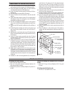
22. Carefully push (31) valve piston into (33) gland to size (34)
seal (see gure 9 below). After sizing, remove (31) valve
piston from (33) gland.
34 - Seal
Direction for sizing
31 - Valve Piston
33 - Gland
16 - “O” Ring
35 - “O” Ring
Figure 8
23. Slide (40) washer over (36) extension rod.
24. Pull (36) extension rod up and grasp with two ngers (see
gure 9 below).
Figure 9
32 Washer
groove
36 Extension Rod
25. Place 90350 special installation tool over (36) extension
rod, with turned diameter down and the chamber side
up.
(continued on page 7)