


Page5of8650110-X
LOWER PUMP SERVICE PROCEDURES
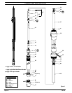
LOWER PUMP DISASSEMBLY
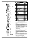
RefertoFigure6.
NOTE: All threads are right hand.
1. Clamp the lower pump assembly in the vise on solid part of (28) pump
body. CAUTION: Clamp the pump so that the three small tubes con-
nected to the lower end of (28) pump body are not being t wisted.
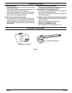
2. Place apipe or strap wrench on theknurled part of the (32) suctiontube
and remove the (32) suction tube. CAUTION: Do not place wrench
any other place other than the knurled part of the (32) suction
tube.
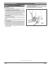
3. Grasp the (41) lower piston rod and remove the rod and piston assem-
bly by pulling straight out.
4. Place a socket wrench in the hex end of the (40) inner suction tube and
remove. CAUTION: Donot use any openend or adjustable wrench.
5. Remove the (30 and 31) gaskets.
6. Loosenthe vise andreclamp thepump on the(28) pumpbody in areaof
material outlet hole. CAUTION:Do not clamp directly onoutlet hole.
7. Remove (27) tube and washer assembly with a strap wrench.
8. Remove the (24) Truarc ring using Truarc pliers.
9. Remove the (25) washer.
10. Remove the (26) “U” c up.
11. Clamp the (49) foot valve body on flats in vise.
12. Place a pipe wrench on the knurled portion of (32) suction tube. CAU-
TION: Do not place wrench any other place other than the knurled
part of the (32) suction tube.
13. Remove (32) suction tube from (49) foot valve body.
14. Remove (49) foot valve body from vise.
15. Remove (47) ball stop.
16. Remove (48) ball.
17. Clamp the (41) lower piston rod in the vise on flats.
18. Place an open end or adjustable w rench on (34) connecting rod flats.
Remove by turning counterclockwise.
19. Remove the (38) washer.
20. Remove the (39) piston.
21. Remove the (46) elastic stop nut.
22. Remove the (45) washer.
23. Remove the (44) piston.
LOWER PUMP END REASSEMBLY
RefertoFigure6.
CAUTION: Apply anti-seizing compound to all stainless steel threads
unless the service manual calls for loctite.
1. Clamp the (41) lower piston rod on flats in vise. Put the (44) piston in
place as shown (lips up).
2. Put the (45) washer and (46) elastic stop nut in place.
3. Place the (39) piston (lips down) on the (41) lower piston rod.
4. Place the (38) washer on the (41) lower piston rod.
5. Thread the (34) connecting rod to (41) lower piston rod and tighten.
6. Clamp on (28) pump body below the three small tubes. Place the (30
and 31) gaskets in the (28) pump body.
7. Thoroughly grease the inside of the (40) inner suction tube and thread
securely into the (28) pump body.
8. Thoroughly grease the (39 and 44) pistons. Insert the (34) connecting
rod through the(40) inner suction tubeand (28) pump body,(33) tip end
first.
9. Thoroughly grease the inside of the (32) suction tube.
10. Insert the (32) suction tube over the (44) piston and thread into the (28)
pump body.
11. Place the (48) ball into the (49) foot valve body.
12. Insert the (47) ball stop into the (49) foot valve body.
13. Thread the (49) foot valve body into the (32) suction tube.
14. Tighten the lowerpump section by placinga bar in the bottomslot in the
(49) foot valve body and turn clockwise.
15. Thoroughly grease and install the (26) “U” cup into the (27) tube and
washer assembly.
16. Place the (25) washer into the (27) tube and washer assembly.
17. Insert the (24) Truarc ring into the (27) tube and washer assembly.
18. Insert the (27) tube and washer assembly over the (33) tip and thread
into the (28) pump body.
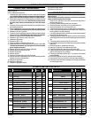
LOWER PUMP END PARTS LIST
Item Description (size) Qty Part No. Mtl Item Description (size) Qty Part No. Mtl
Z Items included in service kit 637028
V Items included in service kit 637029
24 Truarc Ring 1 76243-1 [C]
25 Washer 1 76214 [Br]
ZV 26 “U” Cup (1/8” x 3/4” o.d.) 1 Y186- 4 7 [B]
27 Tube & Washer Assembly 1 60708 [C]
28 Pump Body (66198-X) 1 61617 [C]
(66200-X) 1 61618 [C]
29 Bung Adapter Ass’y (includes 50) 1 60870 [C]
ZV 30 Gasket 1 91419 [Ny]
ZV 31 Gasket 1 91491 [Ny]
32 Suction Tube (66198-X) 1 76245 [C]
(66200-X) 1 76245-1 [C]
33 Tip 1 90826 [C]
34 Connecting Rod (66198-X) 1 92153 [C]
(66200-X) 1 92152 [C]
35 Rod & Heli- Coil Ass’y (includes 34 & 36)
(66198-X) 1 91571
(66200-X) 1 91570
36 Heli-Coil 1 91450 [SS]
37 Rod Assembly (includes 33 & 35)
(66198-X) 1 66254
(66200-X) 1 66253
38 Washer 1 91487 [SS]
Z 39 Piston Kit (66198 & 66200) 1 93848-1 [UH]
V (66198-1 & 66200-1) 1 93848-2 [T]
40 Inner Suction Tube 1 76242 [C]
41 Lower Piston Rod (66198-X) 1 91569 [C]
(66200-X) 1 91569-1 [C]
42 Nut (3/8” - 24) 1 Y11- 106-T [SS]
43 Adapter 1 91485 [SS]
Z 44 Piston (66198 & 66200) 1 91523 [UH]
V (66198-1 & 66200-1) 1 91484 [T]
45 Washer 1 91489 [SS]
46 Elastic Stop Nut (3/8” - 24) 1 Y115-14 [SS]
47 Ball Stop 1 76231 [SH]
48 Ball (0.8125” o.d.) 1 Y16-226 [C]
49 Foot Valve Body (66198-X) 1 76207 [C]
(66200-X) 1 90931 [C]
50 Thumb Screw (1/4” - 20 x 1-1/2”) 1 Y197- 158- C [C]