


Page3of8650110-X
2” AIR MOTOR SERVICE PROCEDURES
2” AIR MOTOR DISASSEMBLY
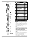
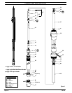
RefertoFigure4.
NOTE: All threads are right hand.
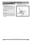
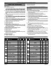
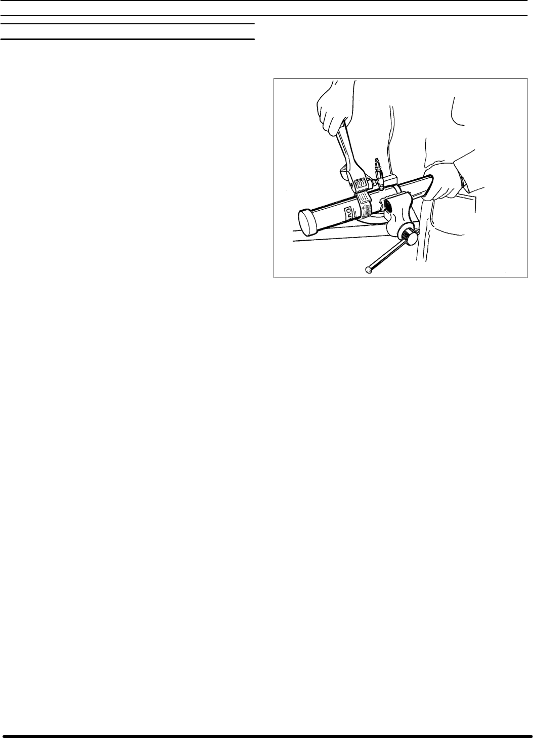
1. Place the air motor in the vise with a needle valve or a 1/4” pipe nip-
ple resting against the jaws of the vise, as shown.
2. Placea strapwrencharound the(1) capandremove thecap. NOTE:
If the (6) cylinder comes off with (1) cap, place the cap in a vise and
use a strap wrench around the cylinder and unscrew from cap.
NOTE: Do not squeeze or use pipe wrench on (6) cylinder.
3. Place a strap wrench around the (6) cylinder and unscrew and re-
move the cylinder.
4. Pull the (7) spacer and piston assembly and (15) plunger out of the
(18) pump body and lay aside.
5. Remove the (17) valve spring and (16) “O” ring from the (18) pump
body.
6. Place the (18) pump body in the vise and loosen the (21) lock ring
with a strap wrench.
7. Place astrap wrench aroundthe (22) separatingtube and unthread.
8. Remove the (20) washer and (19)“O” ring from the (18) pump body.
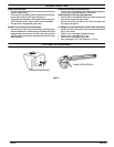
9. Clamp the flatsof the(7) spacerand pistonassembly inthe vise.Re-
move the plunger tip from the (7) spacer and piston assembly.
NOTE: Do not removethe (13) plunger tip from the(15) plunger, un-
less replacing parts.
10. Removethe(12) gasketfrom the(13) plungertip. NOTE:Donot mar
or damage o.d. of (15) plunger.
11. Remove the three (8) screws from the spacer and piston assembly.
12. Remove the (9) valve plate and (11) valve spacer.
Figure 4
S LoctiteR isa registeredtrademark of Henkel LoctiteCorporation S