


Page2of8 650110-X
GENERAL DESCRIPTION
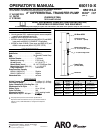
The ARO 2”differential, 2:1ratio transferpumps havebeen designedfor
the application and transfer of a wide range of corrosive and non-corro-
sive materials. Refer to the lowerpump parts list on page 4 for manufac-
tured materials and packings available. These pumps may be directly
mountedin the2” bungofastandard drumorwhen usinga61113mount-
ing bracket, the pump can be mounted on the wall or in an open head
drum.
The air motor is connected to the lower pump end by a spacer tube, this
protectsthe airmotor sectionfrom possiblecontaminationdue tonormal
wear and eventual leakage of material past the upper material piston
seals.
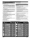
PUMP RATIO X
INLET PRESSURE TO PUMP MOTOR
=
MAXIMUM PUMP
FLUID PRESSURE
Pump ratio is an expression of the relationship between the pump motor area and the
lower pump endarea. EXAMPLE: When150 p.s.i. (10.3 bar) inlet pressure is supplied
tothemotorofa2:1ratiopumpitwilldevelopa maximumof300p.s.i.(21bar)fluidpres-
sure (atno flow) -as the fluid control is opened, the flow rate will increase as the motor
cycle rate increases to keep up with the demand.
Refer to GeneralInformation sheet for safetyprecautions and important
information.
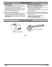
PUMP SER VICE PROCEDURES
PUMP DISASSEMBLY
RefertoFigure2.
NOTE: All threads are right hand.
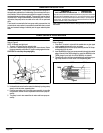
1. Thread a 1/2” nipple into the material outlet.
2. Place the 2” differential pump assembly in a vise as shown. Rotate
the pumpassembly so thatthe 1/2” nippleis resting againstthe vise.
CAUTION: Do not clamp the pump tightly.
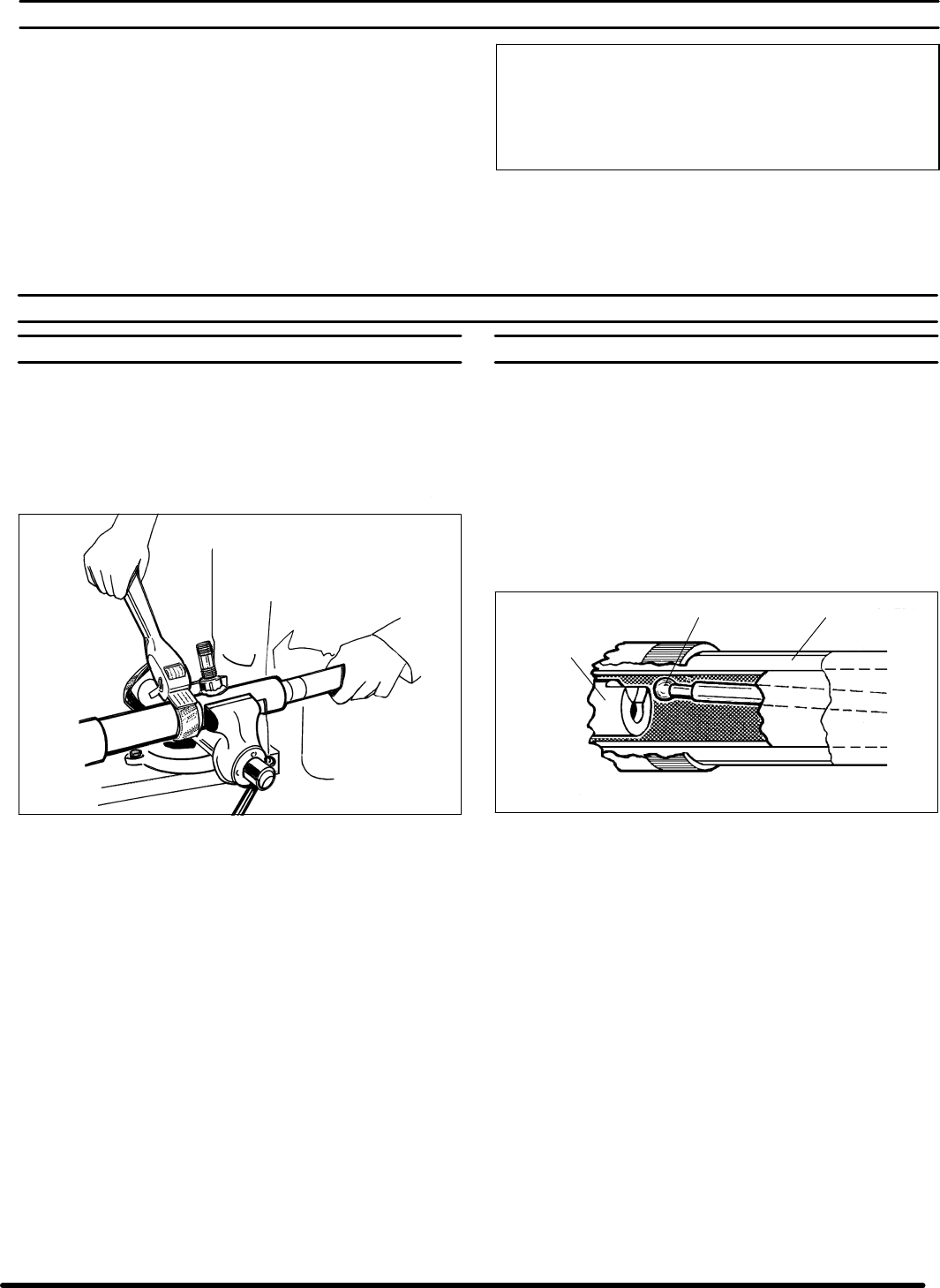
Figure 2
3. Unthread theair motor fromthe material outletbody by usinga strap
wrench on the air motor separating tube.
4. Push the connecting rod, in the lower pump assembly, to one side
and pull down until the air motor separates from the lower pump as-
sembly.
5. The pump is now in two assemblies: air motor and lower pump as-
sembly.
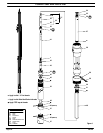
PUMP REASSEMBLY
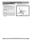
RefertoFigure3.
1. Place the 2” air motor in a vise with the needle valve or pipe nipple
resting against the jaws of the vise, as shown.
2. Insert the 90826 tip ofthe lower pump assembly into the 76216 sep-
arating tube of the air motor.
3. Insert the 90826tip of the lowerpump assembly through theoutside
edge of the slot in the 76208 plunger tip, center the 90826 tip in the
76208 plunger tip and pull out until the 90826 tip is retained.
4. Thread the air motor into the material outlet body and tighten by us-
ing a strap wrench on the air motor 76216 separating tube.
Figure 3
90826 76216
76208