


Page4of8 650110-X
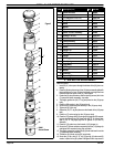
60702 2’’ AIR MOTOR PARTS LIST
1
2
3
4
5
6
8
9
10
11
12
13
14
15
17
18
19
20
21
22
16
7
93005
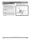
Ground Screw
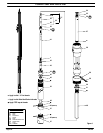
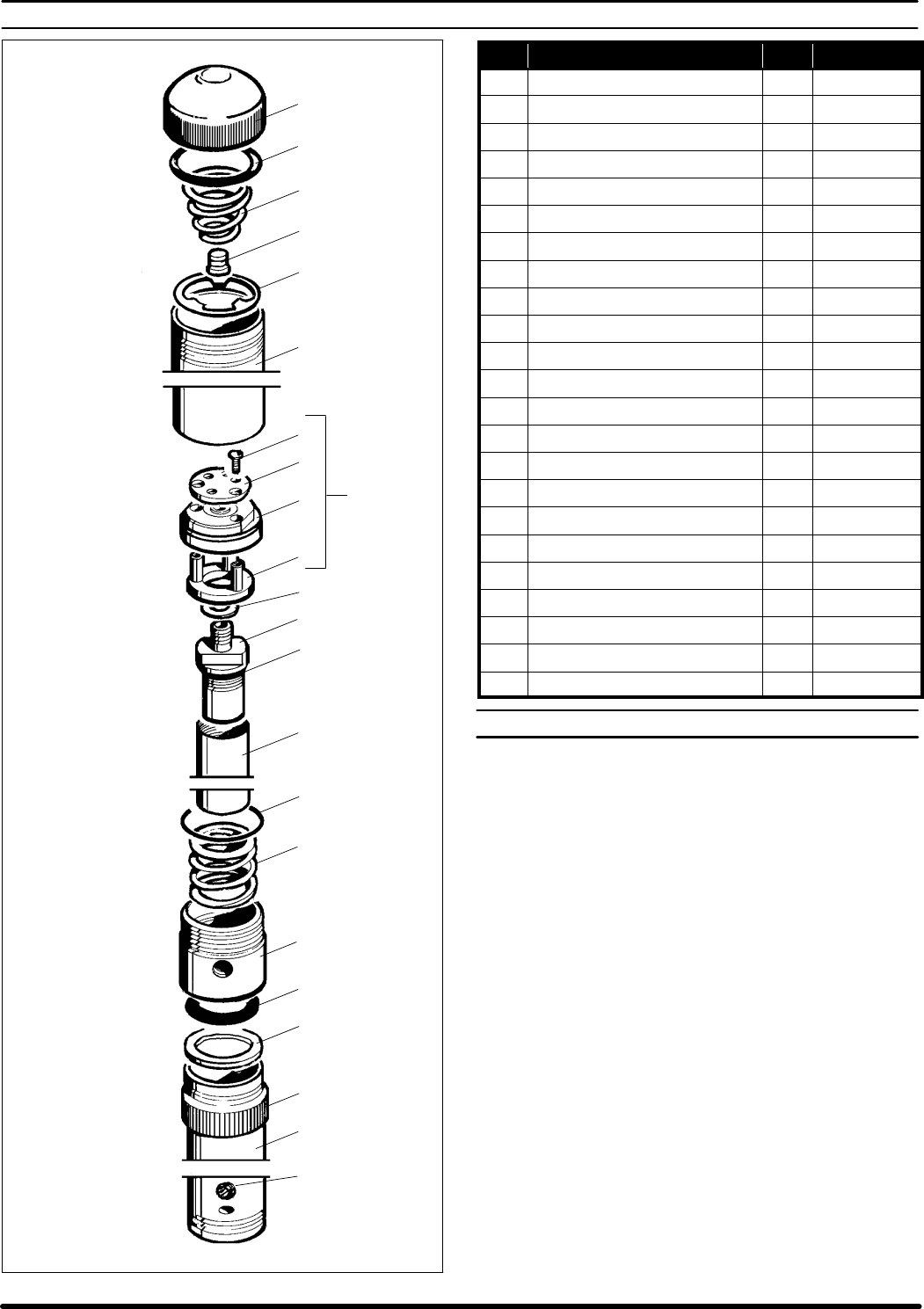
Figure 5
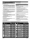
Item Description (size) Qty Part No.
n
Service Kit Parts 66098
1 Cap 1 76073-2
n 2 “O” Ring (3/32” x 2-5/16” o.d.) 1 Y325-138
3 Spring 1 77208
4 Button 1 90638
5 Washer 1 77290
6 Cylinder 1 76074-2
n 7 Spacer & Piston Assembly 1 61088
8 Screw (#4-40x3/8”) 3 Y222-54-C
9 Valve Plate 1 76090
10 Piston Assembly 1 60656
11 Valve Spacer 1 76856
n 12 Gasket 1 F21-53
13 Plunger Tip 1 76208
14 “O” Ring (1/8” x 1-1/4” o.d.) 1 Y325-214
15 Plunger 1 76215
n 16 “O” Ring (3/32” x 2 -1/16” o.d.) 1 Y325-134
17 Valve Spring 1 76070
18 Pump Body 1 76077-2
n 19 “O” Ring (0.275” x 1.837” o.d.) 1 77803
20 Washer 1 76075
21 Lock Ring 1 76100
22 Separating Tube 1 76216
2” AIR MOTOR REASSEMBLY
RefertoFigure5.
1. Insert the (11) valve spacer through the bottomof the (10) piston as-
sembly.
2. Place the (9)valve plateon topof the(10) piston assembly(sidewith
three protrusions) to face (10) piston assembly and align the three
holes with the three posts of the (11) valve spacer.
3. Fasten the (9) valve plate down with the three (8) screws (this is the
(7) spacer and piston assembly). Lay aside.
4. Thoroughly grease the (19) “O” ring and place into the (18) pump
body.
5. Place the (20) washer in the (18) pump body.
6. Screw the (22) separating tube securely to the (18) pump body.
7. Tighten the (21) lock ring.
8. Grease the (16) “O” ring and place over the threads of the (18) pump
body.
9. Place the (17) valve spring into the (18) pump body.
10. Placethe (15)plunger with(13) plunger tipthrough the(22) separat-
ing tube and through the (18) pump body. NOTE: To prevent dam-
age to (19) “O” ring apply light film of grease on (15 and 13)
assembly.
11. Place the (12) gasket over the threads of (13) plunger tip.
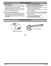
12. Screw the (7) spacer and piston assembly onto the (13) plunger tip
and tighten with wrenches, using flats provided.
13. Thoroughlygrease the inside ofthe (6) cylinder andinsert it over the
(7) spacer and piston assembly.
14. Thread the (6) cylinder on the (18) pump body.
15. Screw the (1) cap, with (2) “O” ring, (3) spring, (4) button and (5)
washer, in place on the (6) cylinder and tighten with a strap wrench.