


PAGE 6 OF 6 613100-X
TROUBLE SHOOTING
No material (stalled pump).
• Obstructed (R) spray tip. Remove spray tip and clean.
• Obstructed(F) hoseassembly. Removecontrol handle andoperate
pump until line is clear.
• Obstructed (G) control handle assembly. Disassemble and clean.
No material (Pump continually cycles).
• Empty material supply. Disconnect the air. Replenish material sup-
ply.Connect theair. Open(G) controlhandle assemblyuntil pumpis
primed.
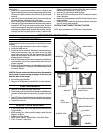
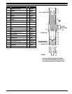
• 90609Retainingscrew(See Figure3)disassembled from(3)plung-
er. (Figure 4). Connect the retaining screw to the plunger. (Follow
instructions for assembly of air motor to lower pump end).
• Damaged (H) lower suction tube. Replace suction tube.
• Loose (J) hose clamp assembly on (K) tube. Tighten clamp.
Material on One Stroke only (Fast Downstroke).
• (20) Ball in (21) foot valve not seating, or damaged (19) “O” Ring.
Remove the foot valve. Remove the ball from the foot valve. Clean
andinspect ballandfootvalve. Ifeitherballor footvalveisdamaged,
replace, also replace (19) “O” Ring if damaged. (See Lower Pump
End Instructions).
Material on One Stroke only (Fast Upstroke).
• Worn (13) “O” Ring. Replace with new (13) “O” Ring. (See Lower
Pump End Instructions).
Material Leakage Out the Oil Daily Holes in Pump.
• Worn (5)packing. Replaceworn packing.(See LowerPump EndIn-
structions).
Air leakage out of the Main Exhaust.
• Worn 90796 valve insert. Replace the valve insert. (See Air Motor
Instructions).
• Loose 65027 Piston Assembly. Tighten piston assembly. (See Air
Motor Instructions).
• Damaged 65027 Piston Assembly. Replace piston assembly. (See
Air Motor Instructions).
• Warpedor worn 65028valve plate andpin assembly.Replace valve
plate and pin assembly.
Continual leakage out of the bleeder hole in the Head Assembly.
• Worn91207 “O”Ringor 91007Seal.Replacethe “O”Ringand Seal.
(See Air Motor Instructions).
Air leakage out of the bleeder hole on the Air Motor Assembly
downstroke.
• Worn Y186-51 “U” cup. Replace the “U” cup. (See Air Motor Disas-
sembly Instructions).
Air leakage out of the Oil Daily Holes in the Pump Section.
• Worn Y325-210 “O” Ring. Replace the “O” Ring. (See Air Motor In-
structions).
Material leakage around the Control Handle.
• Loose76947 gland.Tightenpacking screw.(SeeControl HandleIn-
structions).
• Worn 77516 packings. Replace packings. (See Control Handle In-
structions).
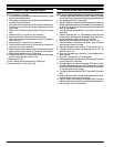
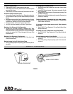
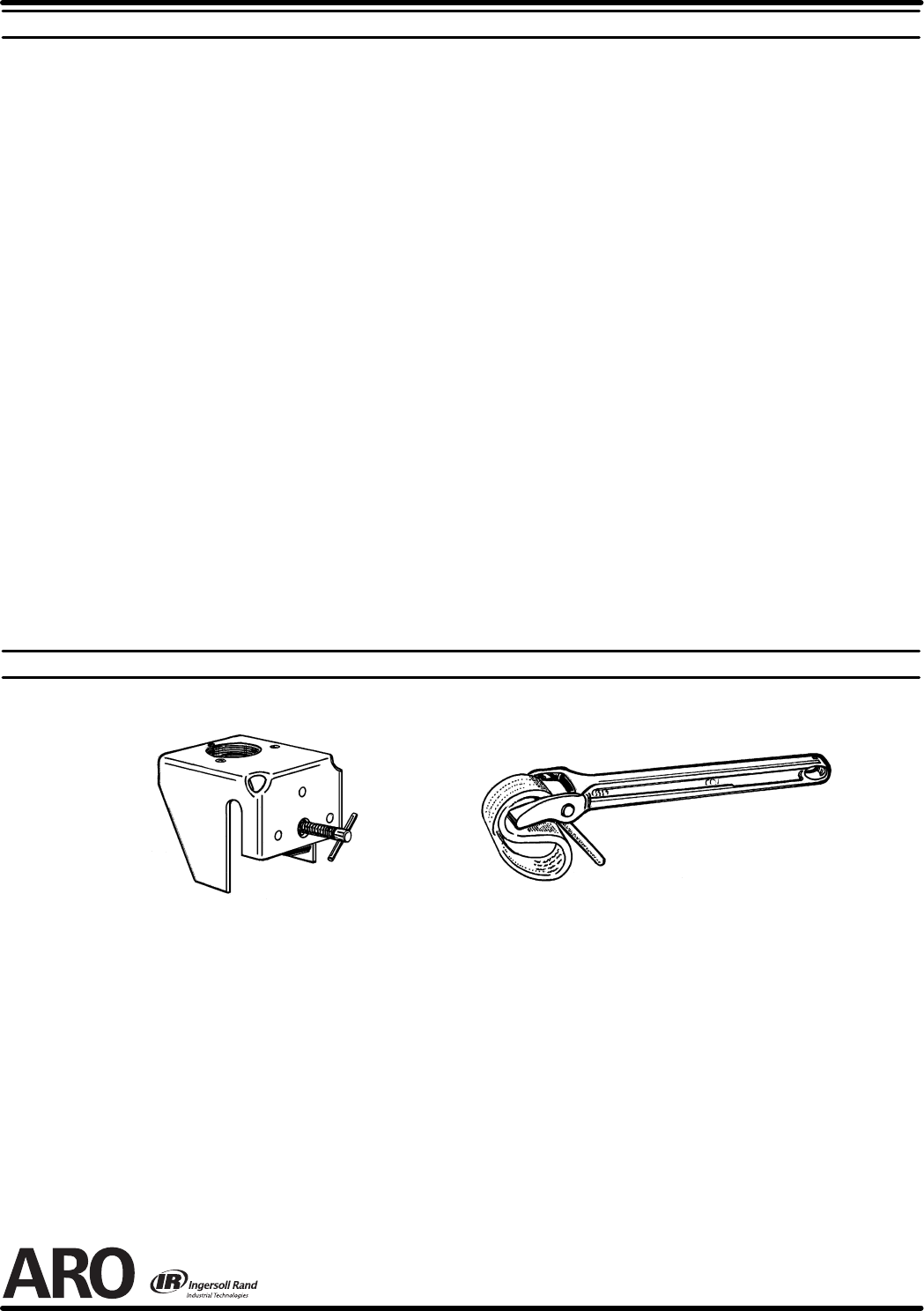
OPTIONAL ACCESSORIES
61113 MOUNTING BRACKET
640081-B STRAP WRENCH
FIGURE 5
PN 97999-92