


PAGE 2 OF 6 613100-X
OPERATING PRECAUTIONS
WARNING
HAZARDOUS PRESSURE. Do not exceed maxi-
mum operating pressure of 1500 p.s.i. (103 bar) at 150 p.s.i.
(10.3 bar) inlet air pressure.
PUMP RATIO X
INLET PRESSURE TO PUMP MOTOR
=
MAXIMUM PUMP
FLUID PRESSURE
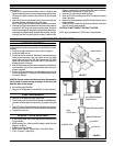
Pump ratio is an expression of the relationship between the pump motor area andthe
lower pumpend area.EXAMPLE: When150 p.s.i. (10.3bar) inletpressure issupplied
tothe motorofa 10:1ratiopump itwilldevelop amaximumof 1500p.s.i.(103 bar) fluid
pressure (at no flow) - as the fluid control is opened, the flow rate will increase as the
motor cycle rate increases to keep up with the demand.
WARNING
Refer to general information sheet for additional
safety precautions and important information.
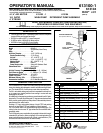
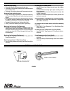
OPERATING INSTRUCTIONS
1. Fill air line lubricator bowl with SAE 90 gear oil.
2. Oil the lower pump assembly section by squirting SAE 90 Gear Oil
into the two holes marked “Oil Daily”.
3. Fill the cleaning solution container with clear water.
4. Connect the air supply line to the air line lubricator.
5. Openthe (G) controlhandle assemblyby squeezing the triggeruntil
water sprays out the spray tip.
6. Adjustair lineoiler to approximately1 drop every 2 minutes by turn-
ing adjusting screw clockwise for less flow.
7. Close control handle.
8. Addtheproper amountof cleaningsolution tocleaningsolution con-
tainer. Insert the (N) bent pipe assembly into the cleaning solution
and openthe control handle assembly. Continue holding the control
handle open until spray from the (N) bent pipe assembly has thor-
oughly mixed the cleaning solution.
NOTE:
• Mostcleaningsolutionswillperformmoreefficientlyinwarmwa-
ter.
• Powdereddetergentswillbeeasierto mixiftheyaredissolvedin
a container of hot water first.
• Consult chemical manufacturer’s recommendations for proper
mixing and concentration
9. Theairsupplyline shouldbe disconnectedwhenthe washpumpas-
sembly is not in operation.
CAUTION: DO NOT ALLOW THE AIR MOTOR TO RUN AFTER THE
SOLUTION CONTAINER IS EMPTIED.
CLEANING INSTRUCTIONS
Use the cleaning instructions supplied by t he cleaning chemical supplier.
General cleaning instructions for detergents and caustics: (In the event
cleaning instructions are not supplied by chemical supplier).
1. Lightly and rapidly cleaning solution to object being cleaned.
2. Let cleaning solution stand on the object for two or three minutes.
3. Starting from the bottom up, clean the object with cleaning solution
holding the spray tip 6 to 8 inches away from object and at approxi-
mately 45_. The 45_ angle will produce a chiseling effect for better
cleaning.
4. Rinse the object thoroughly with clean water from the top down.
General cleaning instructions for aluminum brightening: (If not supplied
by chemical supplier).
1. Applyaluminum brightener to an area of approximately 100 square
feet (approximately 3 semi-trailer panels) from the bottom up.
2. Let the brightening solution soak until light foaming occurs on the
aluminum.
3. Rinse thoroughly with clear clean water from the top down.
CAUTION:Brightening solutionwill etchglassand willburn alumi-
num if permitted to soak after t he light foaming occurs.
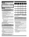
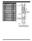
PUMP PERFORMANCE CHART
Operating
Air Pressure
(PSIG)
Spray Tip
Orifice
Pump Back
Pressure
(PSIG)
Air
Usage
(CFM)
Pump
Speed
(CPM)
Flow
Rate
(GPM)
.042 410 5.66 20 .94
50 .052 370 6.62 24 1.16
.062 330 10.35 35 1.72
.042 640 8.75 23 1.09
75 .052 600 12.96 32 1.53
.062 500 19.85 47 2.25
.042 880 13.34 27 1.25
100 .052 800 19.78 37 1.81
.062 720 28.80 56 2.68
.042 1080 20.00 31 1.44
125 .052 1000 26.50 42 2.00
.062 920 40.00 63 3.00
.042 1300 25.50 34 1.59
150 .052 1200 34.32 47 2.19
.062 1100 50.60 68 3.25
PSIG = Pound per square inch gage CPM = Cycles per minute
CFM = Cubic Feet per minute GPM = Gallons per minute
NOTE: Pump should not be operated continuously at speeds in excess
of 60 cycles per minute.
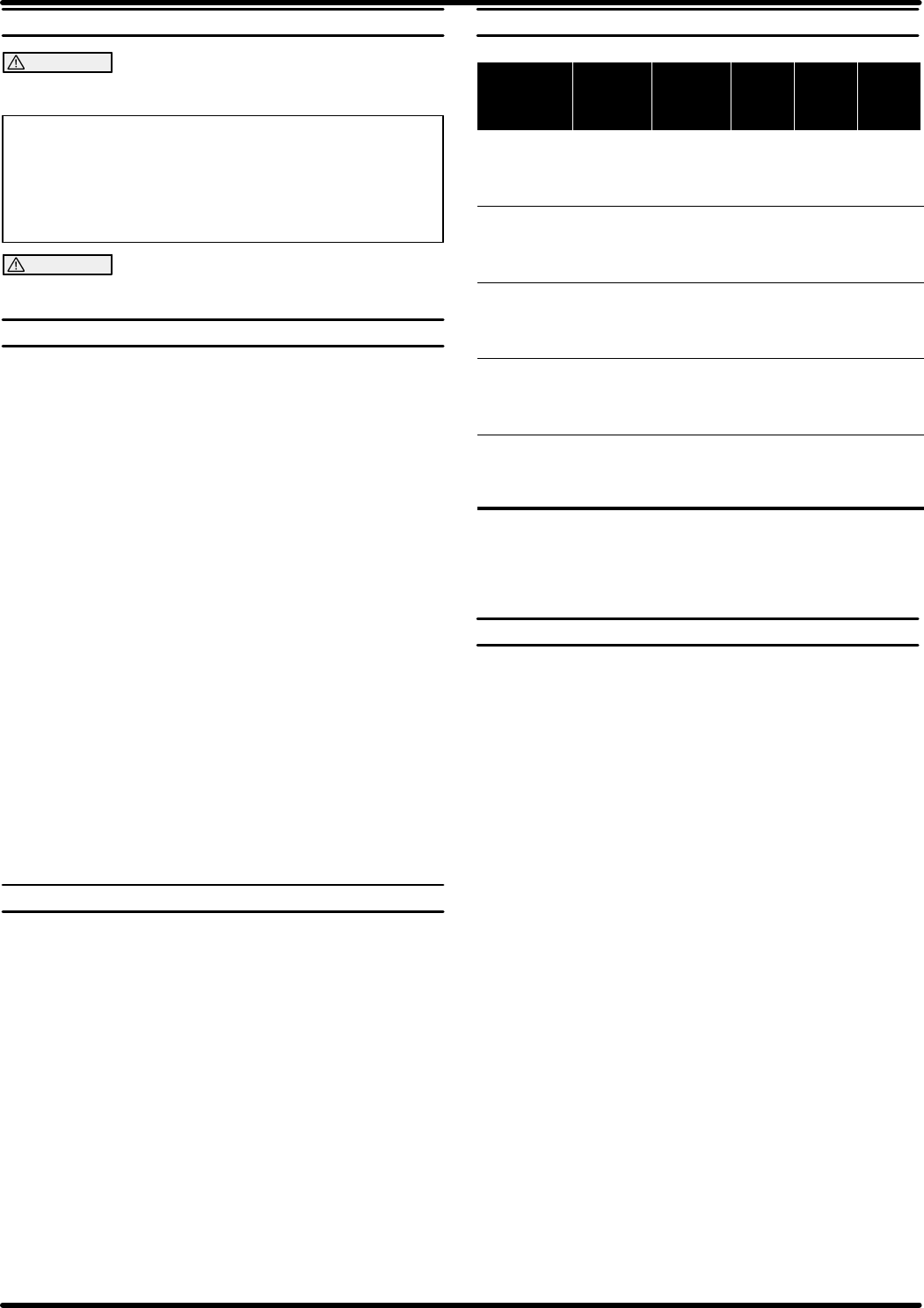
MAINTENANCE
The basicpump consistsof two majorcomponents: 1. AirMotor, 2. Low-
er Pump End. The air motor is connected to the lower pump end by a
spacer tube - this allows access for lubricating t he upper packing gland
in the lower pump end, and to prevent air motor contaminationbecause
of normal wear and eventual leakage through material packing gland.
The air motor is removable and is to be serviced separately. Refer to air
motor manual for service and parts.
• Periodically flush entire pump system with a solvent that is compat-
ible with the material being pump.
• Periodicallyinspect andreplace ifnecessary the(M) screen assem-
bly on the bottom of the (H) suction tube assembly.
• Refer to Disassembly Procedures of air motor and lower pump end
(see Page 3 and 4) for correct breakdown.
• Disassembly should be done on a clean work bench with clean
cloths to keep parts clean.
• If replacement parts are necessary, consult drawing containing
parts for identification.
• Before assembling, lubricate parts where required. When assem-
bling “O”rings or partsadjacent to“O” rings, caremust be exercised
to prevent damage to “O” rings and “O” ring groove surfaces.
Daily Maintenance
1. The airline lubricator should be filled with SAE 90 weight gear oil.
2. Maintain the oil level on the packings in the lower pump assembly.
Use SAE 90 weight gear oil.
3. The air line should be disconnected from the air motor if the pump
sits idle for long periods.