


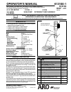
PAGE 3 OF 6613100-X
INSTALLATION
(See Figure 1)
1. Attach the (E) pump bracket assembly to the lip of the drum and
tighten theretaining screw orbolt the pump bracketassembly to the
wall using the 3 holes provided in the back of the (E) pump bracket
assembly.
2. Attach the (H) suction tube assembly to the barbs on the bottom of
the pump assembly and tighten the (J) hose clamp.
NOTE: Soak(K) tubein hot waterfor ease ofinstallation over barbs.
3. Place the (H) suction tube assembly and the lower pump assembly
through the 2” NPT bung in the pump mounting bracket. Thread the
lowerpumpassemblyinto thepumpmountingbracket,align thema-
terialoutletin thedirectionthe(F)materialhoseshouldgo, andtight-
en the (8) lower lock nut. (See Figure 4). Loosen (1) upper lock nut,
(Figure 4),and turn the airinlet of the 65444-B airmotor in the direc-
tion desired and retighten the (1) upper lock nut.
4. Attach the (A) nipple and (B) airline lubricator.
5. Attach the (F) hose assembly to the 3/8 NPT thread in the material
outlet of the pump.
6. Attachthe(F)hoseassembly tothe3/8NPT threadinthe (G)control
handle assembly.
7. Attachthe1/4 NPTthread ofthe (N)bent pipeassembly tothe outlet
of the (G) control handle assembly.
CAUTION: DO NOT CONNECT THE AIR AT THIS TIME.
NOTE: Apply a thread sealer or PTFE tape to all pipe threads.
PUMP SER VICE PROCEDURES
PUMP DISASSEMBLY
To disassemble the lower pump assembly from the 65444-B air motor
assembly:
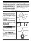
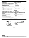
1. Clamp the air motor assembly in a vise as shown in Figure 2.
2. Looses the 90606 lock nut.
3. Place strap wrench around the 76048 spacer tube and remove by
turning counter clockwise. If the strap wrench slips on the 76048
spacer tube, wrap a piece of 400 sand paper around the 76048
spacer tube and under the strap wrench. (NOTE: Pipe wrench will
damage the finish of the tube).
4. Afterthe76048spacer tubehas beenunscrewed fromthe65444 air
motor assembly, pull the lower pump assembly down until the (3)
plunger is exposed.
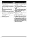
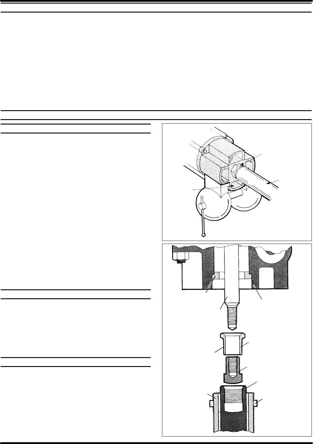
5. Placea1-3/16openend wrenchoran adjustablewrenchon theflats
of the (3) plunger and a 1-1/8 wrench on the 90609 retaining screw
as shown in Figure 3.
CAUTION: Extreme caution should be used when disassembling
the (3) plunger to prevent scoring the plunger. Do not use a pipe
wrench or pliers on the plunger.
6. Set the lower pump end aside.
7. Remove the 76748 gasket from the 65444-B air motor assembly.
PUMP REASSEMBLY
1. Insert the 76748 gasket into the air motor base.
2. Cleanthreads,applyLoctite #242to thethreads ofthe90609 retain-
ing screw and screw them securely into the (3) plunger. See Figure
3.
3. ApplyPTFEtapeor ParkerFerulubeto thethreadsonthe (2)spacer
tube andscrew it intothe 65775air motor baseand insert assembly.
4. Tighten the (1) lock nut.
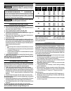
SPECIAL TOOLS AVAILABLE
• 21946Tused to install 76947Packing Screw in641529 and 641523
Control Handles.
• 90350 Inserting Tool. Allows a positive seating to guide Ring and
Adapter in Air Motor.
• 640081-B Aro Strap Wrench.
• 38237 Spanner Wrench. Tightens Seat in Lower Wash Pump.
• 37437-1 Loctite 271 Liquid Lock.
FIGURE 2
LARGE BOSS
90606 LOCKNUT
76048
SPACER TUBE
FIGURE 3
76748 GASKET
90595 ROD
65775 AIR MOTOR BASE
& INSERT ASS’Y
APPLY
LOCTITE #242
90609 RETAINING SCREW
90608 SHOULDER NUT
(3) PLUNGER
(1) LOCK NUT
(2) SPACER TUBE