


PAGE 4 OF 6 613100-X
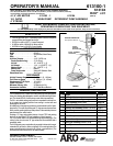
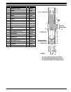
LOWER PUMP SERVICE PROCEDURES
LOWER PUMP DISASSEMBLY
NOTE: All threads are right hand.
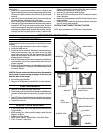
1. Clampthelower pumpassembly inavise sideways onthe (7)pump
body with the material outlet up.
2. With a plastic hammer tap all around the lower end of the (16) suc-
tion tube. (Close to the bottom).
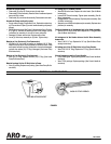
3. Placestrap wrench around the (16) suction tube and hold securely.
Place a wrench on the foot valve body and disassemble from the
suction tube.
4. Remove the (17) dowel pin and (20) ball from the (21) foot valve
body.
5. Remove the (19) “O” ring from (21) foot valve body.
6. Disassemble the (16) suction tube from the pump body.
7. Remove the (3) plunger using extreme caution not to damage the
finish on the O.D.
8. Remove the (9) “O” ring from the (7) pump body.
9. Place the strap wrench on the (2) spacer tube and unscrew the
spacer tube from the (7) pump body.
10. Place awooden dowel or hammer handlein the (2) spacer tubeand
lightly tap the (4) washer, and the (5) packing out of the chamber.
11. Remove the (6) gasket from the (7) pump body.
12. Clamp the flats of the (11) rod in the vise. Remove the (3) plunger
and the (10) lock washer from the (11) rod.
13. Remove the (15) nut.
14. With a spanner wrench remove the (14) retaining nut.
15. Remove the (12) cup and (13) “O” ring.
LOWER PUMP END REASSEMBLY
NOTE: Use anti seizing compound on all stainless steel threads.
1. Thoroughly grease and install the (4) washer, and the (5) packing
into the bore of the (2) spacer tube with the lips toward the opening.
2. Seat the (6) gasket in the (7) pump body.
3. ApplyPTFEtape orParker Ferulubeto the threadson theend ofthe
(2)spacer tubethatthepacking wasinstalledinto, andinsertintothe
top of the (7) pump body (top does not have external threads) and
screw securely together.
4. Thoroughly grease and install the (9) “O” ring into the bottom of the
pump body.
5. Place the (3) plunger (with 1/2 - 20 thread down) into the top of the
(2) spacer tube, and slowly work the plunger through the (5) pack-
ing, until the plunger extends out of the (7) pump body.
6. Place the (10) lock washer over the threads on the (11) rod.
7. Clean the threads of both pieces with solvent, apply Loctite and
screw securely onto the (3) plunger.
8. Slide the assembled (12) cup and (13) “O” ring onto the (11) rod.
9. Thoroughly clean with solvent and apply Loctite to the 7/16 - 20
threads of the (11) rod.
10. Screw the (14) retaining nut onto the (11) rod and tighten with a
spanner wrench.
11. Screw the (15) nut onto the (11) rod and tighten.
12. Pushthe assembled(3) plungerand (12)cup upuntilthe cupcomes
in contact with the (7) pump body.
13. Thoroughly grease the inside of, and apply PTFE tape or Parker
Ferulube to the external threads of the (16) suction tube. Carefully
force the externally threaded end of the suction tube over the (13)
“O” ring and screw into the (7) body.
14. Thoroughlygrease and installthe (19) “O”ring on the(21) foot valve
body.
15. Placethe(20) ballinthe(21) footvalve bodyandinsertthe (17)dow-
el pin into the two holes in the foot valve body.
16. Apply PTFE tape or anti-seizing to the threadsof the(21) foot valve
bodyand screw themintothe (16)suction tubeand tightensecurely.
17. The lower pump end is now assembled.