


1. Unpack the contents of the box. Remove the following materials:
A. Vent Tube - Remove from bubble wrap and insert in hole on top of furnace.
B. Calibration Table Kit - Remove plastic bag containing two tablets and save for future use.
C. Burnout Tray - Remove tray(s) from bubble wrap and install on the floor of the chamber.
2. Place the furnace in position allowing a minimum of 10 inches (25.4 cm) of air space on all sides.
3. Plug the power cord into a wall receptacle. First connect the power cord located on the rear of the furnace.
For large furnaces a dedicated 20A, 115V circuit terminated with a NEMA 5-20 R type receptical is required.
For medium furnaces a dedicated 15A, 115V curcuit terminated with a NEMA 5-15 R type receptical is the
minimum requirement. A 20 AMP circuit is recommemnded.
4. The furnace is now ready for operation.
CAUTIONS:
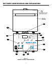
DO NOT BLOCK VENT HOLE ON TOP OF THE FURNACE. Hot gases are vented through
this hole.
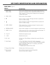
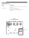
TO SET TEMPERATURE SCALE (Figure 1)
115V furnaces are pre-set in degrees Fahrenheit.
1. Turn the power switch on. (If the furnace is already on, be sure it is in the idle mode - no program is
running.) The chamber temperature appears on the Main Display and the °F light goes on.
2. Press at the same time. The degree light switches to the opposite temperature scale.
UNPACK AND SET-UP
INSTALLATION
7
°
°
VENTING INSTRUCTIONS
Vent fans must have a minimum capacity of 100 cubic feet per minute for each burn out furnace.
If a common hood is used for more than one burn out furnace, fan capacity must be 100 cubic feet per minute for
each square foot of hood opening.
All hoods, vent pipe and ducting components must be constructed of non combustable materials and be installed in
accordance with local building codes.
Maximum expected exhaust temperature is 1800
°F (980°C).
Maximum expected exhaust waste heat is 5,100 BTU’S / Hour or 1,000 Watts.