


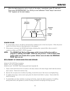

1. Remove the front panel (Figure 5).
2. Note and record the color and location of each wire on the thermocouple terminals located on the Main
PC Board. Remove both wires.
3. Remove the calibration jack connector (J1) from the Main PC Board by pulling straight up.
4. Remove five electrical connectors (BLACK, ORANGE, YELLOW, WHITE, GREEN) from the Main PC Board by
pulling straight up on the connector. DO NOT PULL ON THE WIRES.
5. Remove the nuts and lockwashers that hold the Main PC Board to the front panel and lift straight up to
remove board.
6. Align the holes in the new board with the standoffs on the front panel, reinstall the fasteners and screws.
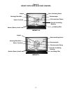
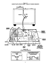
7. Reconnect the electrical connectors as follows:
Black wire to terminal marked “H.” - E5.
Orange wire to terminal marked “GATE.” - E4.
Yellow wire to terminal marked “LOAD.” - E3.
White wire to terminal marked “N.” - E2.
Green wire to ground terminal. - E1.
8. Reconnect calibration jack connector. The green wire on the connector is closest to the bottom edge of the
front panel.
9. Reconnect the two thermocouple wires to the thermocouple terminals observing the color coding noted in
Step 2. If thermocouple wires are reversed, 5 minutes after heating program is started, "Er 5" will appear
on the Main Display.
10. Replace the front panel.
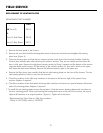
FIELD SERVICE
REPLACEMENT OF THE MAIN PC BOARD
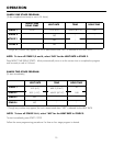
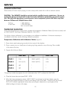
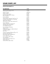
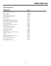
REPLACEMENT PART NUMBERS
23
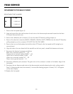
115V
M 15500-041
L 15500-541