


1. Remove the bottom front panel and the upper and lower rear panels of the furnace. (Note the position of
the vent louvers on the rear panels.)
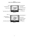
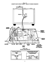
2. Note and record the color and location of the wires on the thermocouple terminals located on the Main
PC Board (Figure 5).
3. Remove the thermocouple wires from the thermocouple terminals on the Main PC Board (Figure 5).
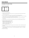
4. Remove the clamp which secures the thermocouple to the ceramic terminal block located in the upper rear
of the furnace (Figure 4).
5. Remove the heating plate wire which crosses over the thermocouple and bend it out of the way just enough
to permit sliding the thermocouple out of the rear of the heating chamber (Figure 4).
6. Remove the insulating filler that covers the holes in the bottom of the upper section (Figure 4). Straighten
the thermocouple wires where they were bent at a 90° angle.
7. Withdraw the thermocouple down into the lower rear of the furnace through the holes in the upper and
lower sections. Discard thermocouple assembly.
8. Feed the new thermocouple from the lower rear of the furnace up through the holes in the upper and lower
sections and into the upper rear of the furnace.
9. Bend the new thermocouple wires at a 90° angle approximately 3 - 3/8 inches (8.6cm) from the exposed
tip of the thermocouple. Be sure that there are three ceramic insulating sleeves between the thermocouple
tip and the bend. Insert the new thermocouple into the hole at the rear of the heating chamber.
10. Replace the heating plate wire that was removed in Step 3. Check that there is a ceramic insulating sleeve
covering the thermocouple wires where they cross the heating plate wire. Replace the clamp that holds the
thermocouple wires to the ceramic terminal block. Replace the insulating filler that covers the holes in the
bottom of the upper section.
11. Connect the thermocouple wires to the thermocouple terminals on the Main PC Board. Observe the color
coding you noted in Step 2.
12. Replace the front panel and the upper and lower rear panels. (Be sure the vent louvers on the rear panels
protrude out and face down.)
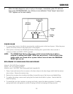
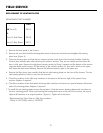
FIELD SERVICE
REPLACEMENT OF THE THERMOCOUPLE ASSEMBLY (PN 18913)
25