iv
Figure B.2: Lead Screw System Inertia Considerations ............................................................A-10
Figure B.3: Rack and Pinion System Inertia Considerations ....................................................A-11
Figure B.4: Conveyor System Inertia Considerations ...............................................................A-11
Figure B.5: Rotary Table System Inertia Considerations ..........................................................A-12
Figure B.6: Chain Drive System Inertia Considerations ...........................................................A-13
Figure B.7: Planetary Gearbox Specifications for MDrive34AC Plus
2 .....................................A-14
Figure B.8: PM105 Planetary Gearbox Specifications for MDrive42AC Plus
2 ........................A-15
Figure B.9: PM120 Planetary Gearbox Specifications for MDrive42AC Plus
2 ........................A-16
Figure C.2: MD-CC300-000 Mechanical Specifications .........................................................A-17
Figure C.1: MD-CC300-000 ..................................................................................................A-17
Figure C.3: Hardware Update Wizard .....................................................................................A-17
Figure C.4: Hardware Update Wizard Screen 2 .......................................................................A-18
Figure C.5: Hardware Update Wizard Screen 3 .......................................................................A-18
Figure C.6: Windows Logo Compatibility Testing ...................................................................A-18
Figure C.8: Hardware Properties .............................................................................................A-19
Figure C.7: Hardware Update Wizard Finish Installation ........................................................A-19
Figure C.9: Windows Device Manager ....................................................................................A-19
Figure C10: Typical Setup, Adapter and Single-End Cordset ...................................................A-20
Figure C.11: MD-ADP-M23 ..................................................................................................A-20
Figure C.12: MD-ADP-M23 Mechanical Specifications .........................................................A-20
Figure C.13: MD-CS10x-000 Prototype Development Cordset ..............................................A-21
Figure C.14: MD-CS20x-000 .................................................................................................A-22
Figure D.1: Internal Differential Encoder Pin Configuration ..................................................A-23
Figure D.2: Differential Encoder Signal Timing ......................................................................A-24
Figure E.1: Speed-Force Limitations ........................................................................................A-25
Figure E.2: Speed-Torque Curves ............................................................................................A-25
Figure E.3: Mechanical Specifications ......................................................................................A-26
List of Tables
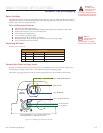
Table GS.1: AC Wire Colors ..................................................................................................... 1-1
Part 1: Hardware Specifications
Table 1.2.1: Setup Parameters .................................................................................................... 1-8
Table 1.2.2: P1- 19-Pin M23 Pin Assignment and Description ............................................... 1-10
Table 1.2.3: P1- 19-Pin M23 Pin Assignment and Description (Internal Optical Encoder) ..... 1-11
Table 1.2.4: P3 - AC Power ..................................................................................................... 1-12
Table 1.4.1: Setup Parameters .................................................................................................. 1-16
Table 1.4.2: P1- 19-Pin M23 Pin Assignment and Description ............................................... 1-18
Table 1.4.3: P1- 19-Pin M23 Pin Assignment and Description (Internal Optical Encoder) ..... 1-19
Table 1.4.4: P3 - AC Power ..................................................................................................... 1-20
Part 2: Interfacing and Configuration
Table 2.1.1: Input Clocks Timing Table .................................................................................... 2-5
Table 2.1.2: Optocoupler Reference Connection ....................................................................... 2-6
Table 2.1.3: Fault Output Specifications ................................................................................... 2-8
Table 2.3.1: Setup Parameters and Ranges ............................................................................... 2-12
Table 2.3.2: Microstep Resolution Settings .............................................................................. 2-15
Table 2.3.4: Input Clock Filter Settings ................................................................................... 2-17
Table 2.4.1: SPI Commands and Parameters ........................................................................... 2-22
Appendices
Table B.1: Planetary Gearbox Operating Factor .........................................................................A-9
Table B.2: Planetary Gearbox Specifications – PM81 ..............................................................A-14
Table B.3: Planetary Gearbox Ratios and Part Numbers ..........................................................A-14
Table B.4: Planetary Gearbox Specifications – PM105 ............................................................A-15
Table B.5: PM105 Planetary Gearbox Ratios, Inertia Moments and Part Numbers .................A-15
Table B.7: PM120 Planetary Gearbox Ratios, Inertia Moments and Part Numbers .................A-16
Table B.6: Planetary Gearbox Specifications – PM120 ............................................................A-16
Table C.1: MD-CS10x-000 Wire Color Chart ........................................................................A-21
Table C.2: Euro AC Wire Color Chart ....................................................................................A-22
Table D1: Available Encoder Line Counts and Part Numbers ..................................................A-23
Table E.1: Linear Slide Specifications ......................................................................................A-26


