


ECR International
Hyundai Ductless Split System13
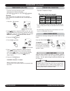
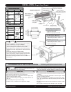
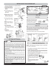
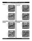
1. Cutting and flaring of
tubing:
A. Cut the tubing on its
straight part with the
pipe cutter.
B. Remove burrs from cut
edges of pipes, which
may cause a gas leak.
C. Flaring of the pipe is
done with the flaring
tool.
NOTE: Do not forget to in-
stall the flare nut before
flaring
2. Pre-Connecting:
Screw the tubing turning
3 to 5 times until hand
tight.
3. Fastening:
Fasten the connection.
• Apply refrigeration oil to
the flare surface to pre-
vent gas leakage.
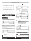
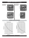
Leak Test
Leak Check
Check the joints with a gas
leak detector or soapy water for
refrigerant leaks. If a leak is
found, repair and recheck.
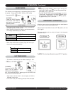
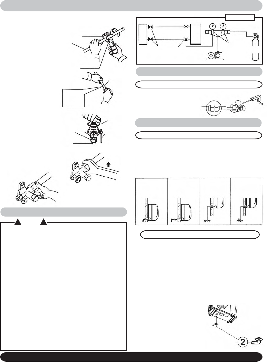
Drainage
Indoor Unit
After the indoor unit(s) have been installed, make sure that
condensed water is properly drained. (If this is neglected,
the unit(s) may become flooded.)
Special care should be given to the following details:
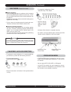
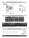
Outdoor Unit (Heat Pump Only)
NOTE: Allow clearance for drainage of water or condensate.
For outdoor condensation:
• The outdoor unit has drain outlets on the base to drain
condensation to the outside.
• To drain condensation by hose (5/8” hose) with the drain
socket, connect the socket to the center of the base and
cover all other outlets with base caps.
• Install the outdoor unit on a flat level surface and make
sure condensation drains smoothly.
• In cold areas, condensation
and defrost water can freeze,
therefore do not use the drain
outlet caps during the cold sea-
son.
• Electrical connection should
only be made by a qualified pro-
fessional.
• See the “Determination of Installing Position”.
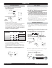
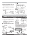
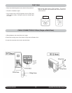
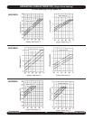
Connecting of Tubing
INSTALLING OF THE OUTDOOR UNIT
1) Remove the cap from the service port on the suction line service
valve.
2) Connect the suction side of the refrigerant gauge manifold to
the Suction Line service valve. Connect the center hose of the
refrigerant manifold gauge to the micron gauge. Connect the
other side of the micron gauge to the vacuum pump. (Diagram 1)
3) Open the suction side of the refrigerant manifold set and turn
the vacuum pump on. NOTE: Evacuate the system down to
400 microns.
4) When the system pulls down to 400 microns turn the vacuum
pump off. Observe the micron gauge: if the system has a leak
the gauge will detect it. If there is a leak, find it, repair it, and
repeat steps 3 and 4.
5) Close the refrigerant gauge manifold valve and disconnect the
vacuum pump from the system.
6) Remove the Suction and Liquid line Service Valve Caps from the
valves.
7) Using an Allen wrench, open the Liquid Line Service Valve until
the valve is in the fully open position. Next do the same for the
Suction Line Service valve. NOTE: Be careful as not to
completely remove the valve core from the valve. This
will result in the release of refrigerant from the system
into the atmosphere!
8) Re-install the caps on both service valves. This completes the
charging of the system.
! CAUTION !
Cut pipe by rotating the
pipe cutter
Pipe
Turn the handle
Clockwise while
pushing it against
the pipe
Pipe cutter
knife
Yoke
Do not dam-
age the in-
side of the
pipe.
Bar
Flare nut
Fix pipe
turning clamp
handle.
Pipe
• Drain hose must
slope downward
to the outdoor
side.
• Do not use a trap
or kink.
• Never put the
end of the drain
hose into the
water.
• Do not tilt up-
ward.
Flare nut Flare valve
Manifold gauges
Charge
cylinder
Discharge
Suction
Vacuum pump
INDOOR
UNIT
OUTDOOR
UNIT
Diagram 1
Air Purge and Charging
(SINGLE ZONE SYSTEM SHOWN)