


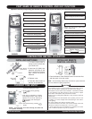
ECR International
Hyundai Ductless Split System12
For Right Rear Sided, Right Sided and Lower
Sided Piping
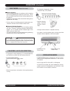
NOTE: Do not apply excessive force to these parts.
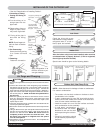
1. For right side and lower side piping, cut the indoor unit
base(s) with a hacksaw and deburr the cut end with a
file. (See Fig. 5)
2. Hang the indoor unit(s) on the upper portion of the instal-
lation plate while inserting the vinyl-taped pipes through
the wall hole. Engage the lower projection with the claws
of the installation plate. (See Fig. 7)
NOTE: Make sure that the unit(s) are securely mounted, by
slightly shaking the indoor unit(s).
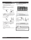
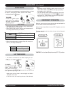
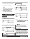
The length of the cable
which will be passed
through the wall hole
should be longer than 40”.
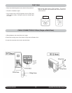
1. Regarding the left rear sided and left sided piping, the pipes
must be connected indoors and must be adjusted to the
actual installing length. Keep these pipes unrolled (See
Fig. 9 and Fig. 10)
2. For left side piping, cut the indoor unit base(s) with a hack-
saw and deburr with a file.
3. Connect the indoor pipes and check for gas leaks.
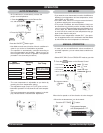
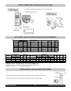
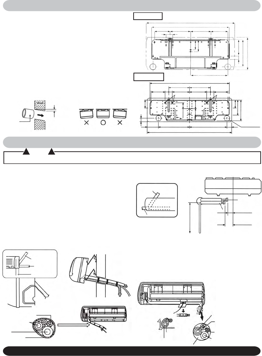
MOUNTING OF THE INSTALLATION PLATE
INSTALLATION OF THE INDOOR UNIT(S)
! CAUTION !
For Left rear Sided and Left Sided Piping:
(See Fig. 8)
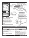
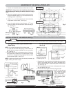
1. Position the installation plate and check that it is level.
IMPORTANT: Always mount the installation plate horizon-
tally by aligning the marking line with the thread or using a
level.
2. Mount the installation plate horizontally and securely on
structural members (studs, etc.) in the wall with four (4)
installing screws. (See Fig. 1)
3. Make a 2
9
/
16
” hole through the wall. Hole should be
angled down to the exterior. (See Fig. 2)
4. Use a city grade wall pipe (outer diameter : 2
3
/
8
”) as a
sleeve to protect the interconnection cable and the pip-
ing. (See Fig. 2)
When inserting the pipes, protect the ends from dust or moisture by covering the flare connections with a cap or tape.
(Take care not to twist or crimp pipes during installation.)
Fig. 1
Fig. 2
18/24 Btuh
9/12 Btuh
Pipe hole Ø 2.56”
1.93”
Anchor plug hole
Anchor plug hole
3’ 4”
18.74”5.04”
3’ 2”
10.33” 10.33”
15.63”
8.52” 8.52” 6.63”
6.63”
1.81”
1.81”
1.81”
1.81”
1.40”
3.93”
2.92”
4.31”
3.72”
3.93”
7.44”
9.84”
3.43”
4.21”
1.18”
5.53”
9.12”
10.83”
2’ 6”
2’ 2.25”
5.28” 6.89” 6.89”
5.79”
1.38” .85”
12.60”
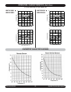
Fig. 8
Left rear sided
Left sided
Fig. 9
Suction pipe
Discharge pipe
Dimensions from the
center of the installa-
tion plate for reference.
4”
6”
Fig. 2
Fig. 3
Wall pipe
( field supplied
OD: 2 3/8”)
Wall-Hook Plate Mounting
Approximately
3/16”– 3/8”
Indoor Outdoor
Flare Coupling
installation
Band
Tape after
finishing
leak test
Discharge pipe
Suction pipe
Suction pipe
Discharge pipe
Interconnection cable
Indoor unit drain hose
Wall hole
Fig. 10
(See Fig. 10) After the leak
test, wrap the flared
joints with insulation
and fix it with bands.
4. Remove the spacer
from installation plate.
Fig. 4
Fig. 5
Fig. 6
Fig. 7
Right rear sided
(recommended)
Right sided
Lower sided
Cut here
Hacksaw
Interconnection cable
Indoor unit pipes
Indoor unit drain
hose
Vinyl tape