


ECR International
Hyundai Ductless Split System11
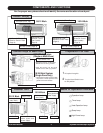
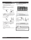
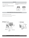
INSTALLATION (Single Zone Shown)
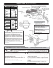
• Make sure that the indoor unit(s) are installed high enough, over
6 feet, (beyond reach of young children).
Indoor Unit
• Do not install the unit(s) near a heat source.
• Be sure that air outlet and inlet are not obstructed.
• Be sure all clearances are as specified in the above figure (front,
upper, left and right of the unit(s)).
• Allow convenient drainage and piping connection with the out-
door unit.
• Avoid installing the unit(s) in direct sunlight.
• Install the unit(s) on walls that can support their weight.
! CAUTION !
• Read this installation manual thoroughly before installing
the air conditioner(s) for proper installation.
• All field wiring must be installed by a licensed electrician
and must comply with all national and local codes.
• All field piping must be installed by a licensed refrigeration
technician and must comply with all national and local
codes.
• Never plug unit(s) into an electrical outlet.
• Do not touch compressor, pipes and valves without pro-
tective gloves during and after operation, because these
parts may become hot (more than 100°C (212°F).
• Explain the operating procedure of the air conditioner to
the customer.
! CAUTION !
DETERMINATION OF INSTALLING POSITION
Install the Air Conditioner(s) by taking into account
the following points, upon the customer’s consent.
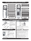
No. Part Qty
1
Remote Control
1/unit
2
Remote Control
Fixture
1/unit
3
Batteries 'LR03'
(AAA)
2/unit
4 Manual 1
No. Part Qty
9/12 Btuh
Rubber Cushion
18/24 Btuh
Rubber Cushion
3
Drain Pipe
1
1
2
Parts of Indoor Unit
Parts of Outdoor Unit
4
4
• Be sure chosen location can properly support the weight of the
unit(s) and will provide adequate damping of vibration and noise.
Outdoor Unit
• Insure chosen location can provide adequate drainage and good
ventilation.
• Do not install in an area with flammable or corrosive vapors. Avoid
salty air or sulfuric gas areas.
• Be sure all clearances are specified in the above figure (front,
upper, left, right and rear of the unit) and also open on more than
two sides.
• Be sure hot exhaust and noise does not bother the customer or their
neighbors.
• Do not allow hot exhaust to blow directly on pets and plants.
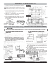
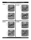
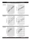
NOTE: Always check superheat
and subcooling of system.
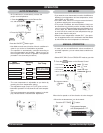
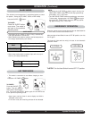
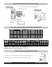
(22.72”) 9/12 Btuh
(23.94”) 18/24 Btuh
(8.86”) 9 Btuh
(11.02”) 12 Btuh
(14.25”) 18/24 Btuh
Outdoor unit mounting
leg dimension
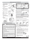
Distance between the
unit(s) and ceiling should
be more than 2”
Clearance in front of unit(s)
should be no less than 10’
Distance between the
unit(s) and the wall should
be more than 6”
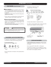
Fasten the unit(s)
on the lower hook
of wall plate
Fasten the unit(s) on the
upper hook of wall plate
Distance between
the unit(s) and the wall
should be more than 6”
Wall plate
Patch
Outgoing tubing
(bottom)
Wall cap
Connecting wire
Through the wall
tubing (O.D. 2.36”)
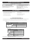
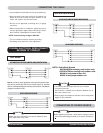
• Height limit: below 25ft.
• Maximum tubing length: below 50ft.
Tubing length over 25ft.
9/12 Btuh (Single or Multi-Zone)
• Charge additional refrigerant amount,
additional refrigerant amount =0.22oz./ft.>25’.
18/24 Btuh (Single Zone Only)
• Charge additional refrigerant amount,
additional refrigerant amount =0.44oz./ft.>25’.
• Capacity drops slightly.
More than 12”
More than 2”
More than 16”
More than 4”
More than 10”