


5-4 108548_0711
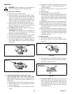
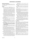
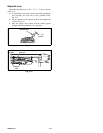
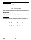
Throttle lever adjustment
Adjust the throttle lever so that when it is placed in the
“CHOKE” position the engine choke is engaged. Fig. 5-5
1. Confirm that the adjustment hole on the engine control
panel matches the throttle lever when it is in the “FAST”
position.
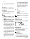
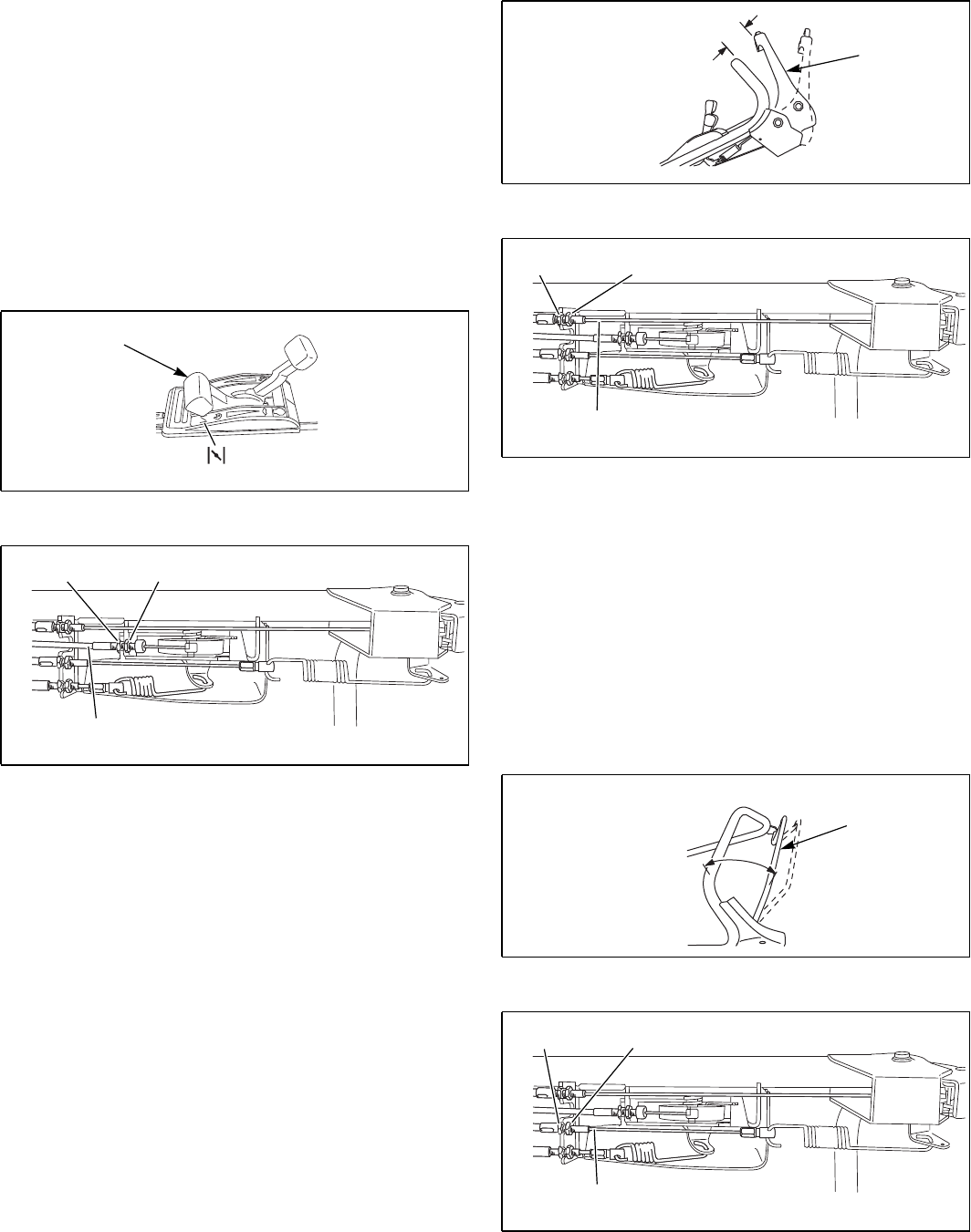
2. If adjustment is necessary, adjust by turning the adjuster
and loosening the lock nut on the throttle cable. Fig. 5-6
3. Set the adjuster to the optimal position and tighten the
lock nut. Fig. 5-6
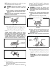
4. Start the engine and confirm that the engine stops
completely when the throttle lever is set at the “STOP”
position.
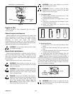
Blade lever adjustment
Adjust so that the blade starts rotating when the distance
between the blade lever and the handle is 1.97” - 2.95” (50 - 75
mm) when the yellow button is depressed. Fig. 5-7
1. If adjustment is necessary, adjust by turning the adjuster
and loosening the lock nut on the blade cable. Fig. 5-8
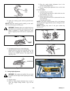
2. Set the adjuster to the optimal position and tighten the
lock nut. Fig. 5-8
3. Confirm that the blade stops completely when the blade
lever is released.
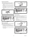
Drive clutch lever
Adjust so that the machine runs (when the drive clutch is
engaged) when the distance between the drive clutch lever and
the handle is 2.95” - 3.94” (75 - 100 mm). Fig. 5-9
1. If adjustment is necessary, adjust by turning the adjuster
and loosening the lock nut on the drive clutch cable.
Fig. 5-10
2. Set the adjuster to the optimal position and tighten the
lock nut. Fig. 5-10
3. Confirm that the machine can be pulled backward when
the drive clutch lever is released.
Fig. 5-5
Fig. 5-6
Throttle lever
Adjuster
Lock nut
Throttle
cable
Fig. 5-7
Fig. 5-8
Fig. 5-9
Fig. 5-10
1.97” - 2.95”
(50 - 75 mm)
Blade lever
Adjuster Lock nut
Blade
cable
2.95” - 3.94”
(75 - 100 mm)
Drive clutch
lever
Adjuster
Lock nut
Drive clutch cable