


21
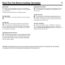
Mount Wallplate and Thermostat
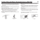
Snap open the wallplate from the thermostat. Disconnect connector 1
and 2 by pulling the leads from the terminal socket. (Figure 2)
Position wallplate on wall and pull existing wires through large opening.
Then level for appearance. Use any two of the many rectangular holes provid-
ed on the wall plate for mounting. Mark holes for plastic anchors provided if
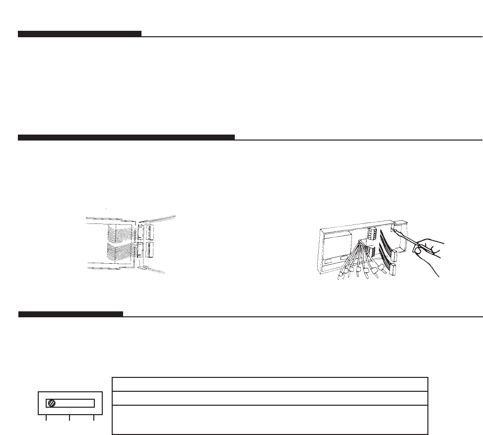
Selector Switch
existing holes do not line up with the Hunter Thermostat holes. (Figure 2A)
Drill holes with 3/16" bit, and gently tap anchors into the holes until
flush with wall.
Reposition wallplate to wall, pulling wires through large opening. Insert
mounting screws provided into wall anchor and tighten.
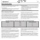
There are three types of heat pump connections relating to the reversing valve. Look for this switch on the printed circuit board.
FIG. 2A
Label Wires (cont.)
O Activates in cool mode RO
B Activates in heat mode RB
W Connection made internally.
No terminal at thermostat (no O or B terminal marked) – NR
instead, there is a separate connection for 1st stage heat.
If the wire is
connected to Reversing Valve Function Set Selector Switch To
NR RB RO
FIG. 2
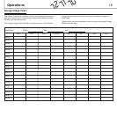
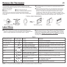
The number of wires in the system can be as few as four (for single stage
heat pump systems), as many as eight, or any number in between for
multistage heat pump systems. If you follow the labeling procedures
correctly, you don't have to be concerned about how many wires there are.
■ Remove existing wallplate. To make sure wires do not fall back into
wall opening, tape them to the wall.
■ If hole in wall is larger than necessary for wires, seal this hole up so
no hot or cold air can enter the back of the thermostat from the
wall. This air could cause a false thermostat reading.
■ After labeling wires, disconnect them from the existing thermostat
terminals.